Building steel bar rust remover

A technology for building steel bars and derusting machines, which is applied to the parts of grinding machine tools, grinding machines, grinding/polishing equipment, etc. It can solve the problems of difficult work, spraying rust removers to the edges of steel bars, troublesome operation, etc., to achieve The effect of reducing work difficulty, simple operation and convenient movement

Active Publication Date: 2020-03-27
中辰鸿泰建设有限公司
View PDF6 Cites 2 Cited by
  • Summary
  • Abstract
  • Description
  • Claims
  • Application Information

AI Technical Summary

Problems solved by technology

[0003] At present, the staff usually carry the sprayer on their backs, and then hold the nozzle of the sprayer to spray the rust remover on the steel bar to derust the steel bar. After spraying one side, the staff will derust the other side of the steel bar. The operation is troublesome, and some steel bars are installed on the edge of the roof. Therefore, it is difficult for the staff to spray the rust remover to the edge of the steel bar, and the work is difficult

Method used


Image

  • Building steel bar rust remover
  • Building steel bar rust remover
  • Building steel bar rust remover

Examples


Embodiment approach 1

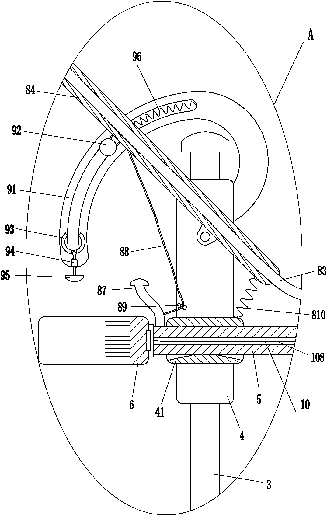
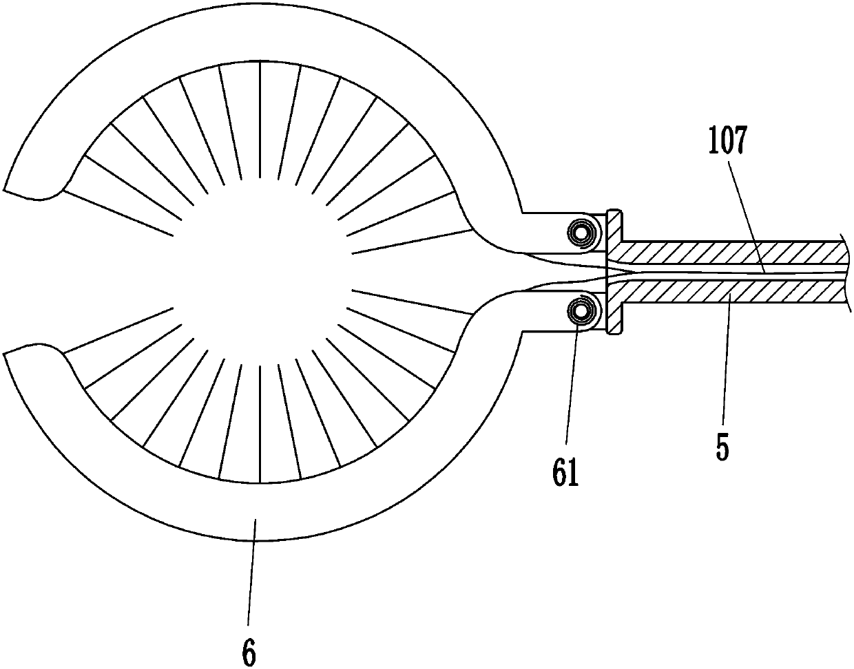
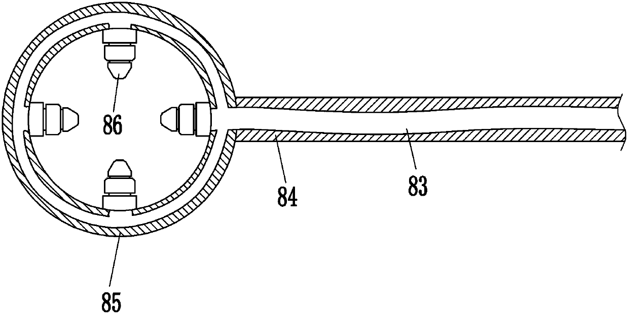
[0024] A construction steel bar derusting machine, such as figure 1 , figure 2 and Figure 5 As shown, it includes a support plate 1, a sliding rod 3, a sliding sleeve 4, a guide sleeve 41, a hollow guide rod 5, a wire brush 6, a torsion spring 61, a handle 7, a spray assembly 8 and a clamping assembly 9, and the support plate 1 There is a positioning groove 2 on the left side, and the top of the support plate 1 is bolted with a sliding rod 3 that acts as a guide. A sliding sleeve 4 is slidingly provided on the sliding rod 3. A guide sleeve 41 is installed on the lower part of the front side of the sliding sleeve 4. The guide sleeve 41 The inner sliding type is provided with a hollow guide rod 5, and the left end of the hollow guide rod 5 is rotationally connected with two wire brushes 6. Torsion spring 61, the right side of the top of the hollow guide rod 5 is connected with a handle 7, the upper part of the front side of the sliding sleeve 4 is provided with a spray assem...

Embodiment approach 2

[0031] On the basis of Embodiment 1, such as figure 2 and Figure 4 As shown, a pulling assembly 10 is also included, and the pulling assembly 10 includes a sliding sleeve 101, a sliding rod 102, a third spring 103, a clamping rod 104, a touch block 106 and a pull cord 107, and the right part of the hollow guide rod 5 is installed with The sliding sleeve 101 that plays a guiding role, the sliding sleeve 101 is slidingly provided with a sliding rod 102, the sliding rod 102 is wound with a third spring 103, one end of the third spring 103 is connected with the sliding sleeve 101, and the other end of the third spring 103 is connected with the sliding sleeve. The rod 102 is connected, the left end of the sliding rod 102 is rotatably connected to the clamping rod 104, the left side of the clamping rod 104 is connected to the pull rope 107, the two wire brushes 6 are connected to the pull rope 107, and the right side of the bottom of the hollow guide rod 5 has a special-shaped gro...


PUM


Abstract

The invention relates to a rust remover, in particular to a building steel bar rust remover. The invention aims to provide the building steel bar rust remover which can remove rust of a whole steel bar at one time, is simple to operate and can reduce the working difficulty. The building steel bar rust remover comprises a supporting disc, a sliding rod, a sliding sleeve and the like; a positioninggroove is formed in the side surface of the supporting disc, the sliding rod for guiding is bolted on the top of the supporting disc, and the sliding sleeve is arranged on the sliding rod in a slidingmode. The steel bar can be derusted through a spraying assembly, a wire brush can scrape off iron rust on the steel bar, so that a derusting agent and the steel bar can make full contact, the derusting of the steel bar is more effective, the whole steel bar can be derusted at one time, the operation is simple, the working difficulty can be reduced, the wire brush can make full contact with the steel bar through a pulling assembly, and the iron rust on the steel bar can be scraped more thoroughly.

Description

technical field [0001] The invention relates to a rust remover, in particular to a construction steel bar rust remover. Background technique [0002] Rebar is steel used for reinforced concrete and prestressed reinforced concrete. Its cross-section is generally circular. Rebar is widely used in the construction industry. It is poured together with concrete to make the building more stable. If the rebar is exposed to the air for a long time, its surface will Rust is very unfavorable to buildings, so it is necessary to derust the steel bars. [0003] At present, the staff usually carry the sprayer on their backs, and then hold the nozzle of the sprayer to spray the rust remover on the steel bar to derust the steel bar. After spraying one side, the staff will derust the other side of the steel bar. The operation is cumbersome, and some steel bars are installed on the edge of the roof. Therefore, it is difficult for the staff to spray the rust remover to the edge of the steel b...

Claims


Application Information

Patent Timeline
Patent Type & Authority Applications(China)
IPC IPC(8): B24B27/00B24B27/033B24B47/20B24B47/22B24B57/02C23F11/02
CPCB24B27/0076B24B27/033B24B47/20B24B47/22B24B57/02C23F11/02
Inventor 李慧芬
Owner 中辰鸿泰建设有限公司
Why Eureka
Try Eureka