Cleaning and derusting device and method for water cavity system

A technology of water chamber and cleaning liquid, which is applied in the field of cleaning and derusting, cleaning and derusting devices for water chamber systems, can solve the problems of easy rusting in the cooling water system of maintenance equipment, etc., so as to adapt to cleaning and derusting, ensure normal operation, The effect of convenient mobile operation

Inactive Publication Date: 2017-02-01
CSSC MES DIESEL
View PDF4 Cites 2 Cited by
  • Summary
  • Abstract
  • Description
  • Claims
  • Application Information

AI Technical Summary

Problems solved by technology

[0004] The purpose of the present invention is to overcome the incomplete derusting of the existing protection methods and cause the maintenance equipment cooling water system to rust easily, and provide a cleaning and derusting device and method for the water chamber system. The cooling water system of the equipment constitutes a complete circuit. The method of adding derusting agent into the cleaning water tank and heating it is used to pressurize the warm and efficient derusting liquid to clean the cooling water system of the maintenance equipment, so that complex water chambers are included. The entire set of cooling water system can be effectively derusted, and the subsequent effective protection of the cooling water system can be ensured through the adhesion of the derusting fluid, so as to ensure the normal operation of the cooling water system

Method used


Image

  • Cleaning and derusting device and method for water cavity system
  • Cleaning and derusting device and method for water cavity system
  • Cleaning and derusting device and method for water cavity system

Examples


Embodiment

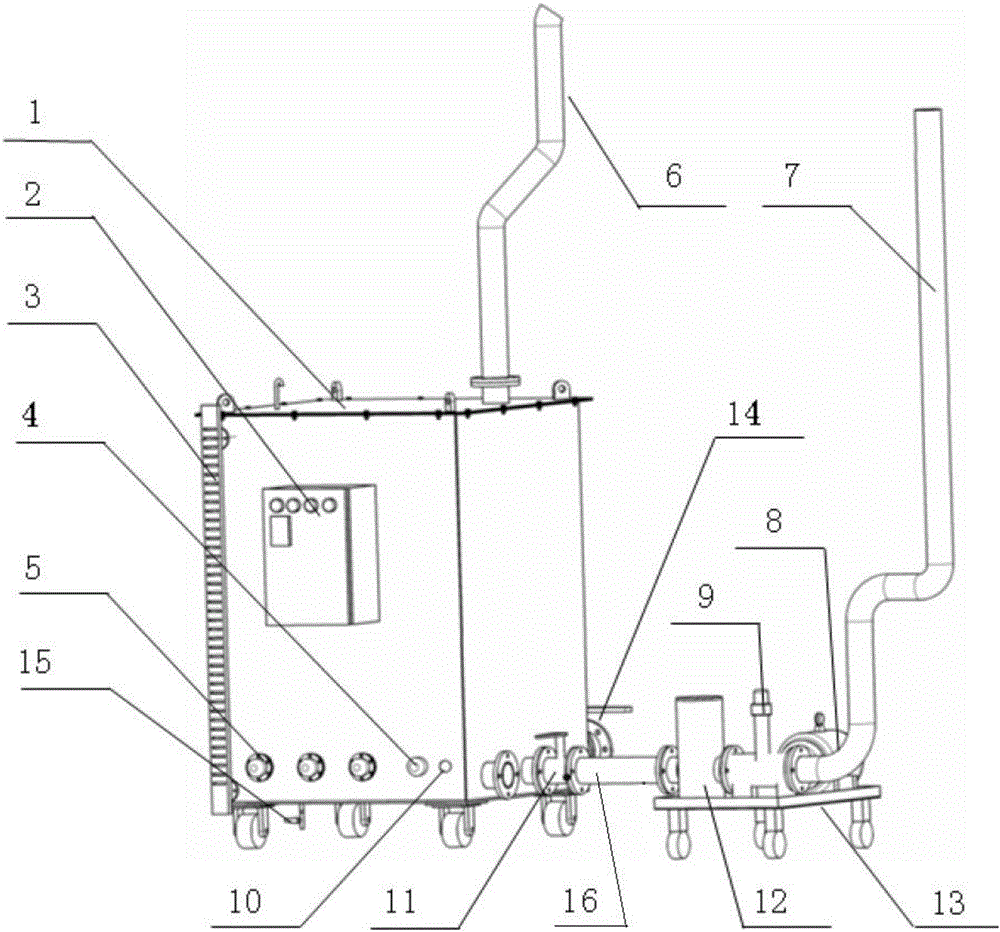
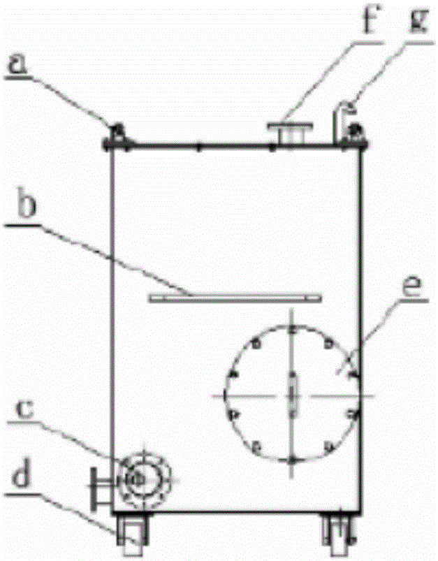
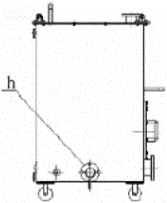
[0038] Please refer to figure 1 , figure 2 and image 3 , which shows that the cleaning and derusting device for the water chamber system is connected with the cooling water system of the maintenance equipment to form an integral circuit, which includes a flushing water tank 1, a filter 12, a centrifugal pump 9 and an electrical unit 2.

[0039]The inside of the flushing water tank 1 contains a cleaning solution containing a rust remover, which is the basis for derusting the cooling water system, and is composed of fresh water and rust remover added to the flushing water tank 1 . The side of the lower part of the flushing water tank 1 is provided with a water outlet h, and the top is provided with a water return port f, and the water return port f is flange-connected to the return water end of the cooling water system of the maintenance equipment through the return water pipe 6 . The top of the flushing water tank 1 is provided with a ventilation pipe g for hydraulic ventil...


PUM


Abstract

Disclosed is a cleaning and derusting device for a water cavity system. The cleaning and derusting device is connected with a cooling water system of maintenance equipment to form an integrated loop. The cleaning and derusting device comprises a flushing water tank, a filter, a centrifugal pump and an electric unit, wherein the flushing water tank is provided with a water outlet and a return water opening, cleaning liquid containing a deruster is contained inside the flushing water tank, heating pipes for heating the cleaning liquid and a temperature sensor for detecting the temperature of the cleaning liquid are disposed on the lower portion of the flushing water tank, and the return water opening communicates with the cooling water system of the maintenance equipment; one end of the filter is connected with the flushing water tank; the centrifugal pump is driven by a motor so as to pressurize the cleaning liquid, one end of the centrifugal pump is connected with the other end of the filter, and the other end of the centrifugal pump communicates with the cooling water system of the maintenance equipment; and the electric unit controls the centrifugal pump to drive the pressurized warm cleaning liquid to circularly flow, so that no-dead-corner overall cleaning and derusting are performed on the cooling water system, and the residual cleaning liquid attached to the interior of the cooling water system after cleaning plays a subsequent antirust role. By means of the cleaning and derusting device for the water cavity system, thorough, overall and effective cleaning and derusting can be performed on the cooling water system provided with a complicated water cavity, and subsequent effective protection of the cooling water system is guaranteed.

Description

technical field [0001] The invention relates to cleaning and rust removal of various water delivery pipelines and water chamber systems, in particular to a cleaning and rust removal device and method for water chamber systems, belonging to the technical field of mechanical manufacturing. Background technique [0002] A variety of industrial production equipment involves a cooling water system, which usually consists of a cooling water piping system and various water chambers that need to cool the body. Due to the different sizes and structures of various equipment, some cooling water piping systems have the characteristics of long piping, winding directions, and complex water chambers. Industrial equipment, especially large-scale equipment, generally goes through the stages of commissioning and trial running, dismantling for shipment, and transport to the place of use for installation and reuse after the main engine assembly. Often due to the difficulty of completely draini...

Claims


Application Information

Patent Timeline
Patent Type & Authority Applications(China)
IPC IPC(8): C23G3/04
CPCC23G3/04
Inventor 李亮顾裕峰焦雷史章磊
Owner CSSC MES DIESEL
Why Eureka
Try Eureka