Vehicle air conditioning system and condensate water recycling system thereof

A vehicle air conditioner and condensate technology, which is applied in the field of vehicles, can solve the problems of reduced condensate flow, less condensate, and high power consumption of compressors, so as to reduce power consumption, prevent overfilling of water storage, and ensure secondary utilization Effect

Active Publication Date: 2020-03-27
GREAT WALL MOTOR CO LTD
View PDF9 Cites 3 Cited by
  • Summary
  • Abstract
  • Description
  • Claims
  • Application Information

AI Technical Summary

Problems solved by technology

For example, for the first solution, the condensate water of the air conditioner becomes longer with the pipeline, and when the temperature reaches the radiator, due to the influence of the pipeline layout and structure, the actual temperature of the condensate water has risen to more than ten or twenty degrees. The cooling effect of the condenser water cannot be exerted, and the temperature of other components will not be lowered, and the temperature may be higher than that of other components, which will bring negative effects on the contrary.
[0008] 2. Condensed water is the water produced by the air on the surface of the air conditioner evaporator due to cooling. The amount of condensed water is related to the humidity of the air and the temperature of the air conditioner. If the air conditioner is relatively dry and the humidity is low, there will be little condensed water. It will reduce the flow rate of condensed water, unable to cool down other radiators, or the cooling effect is poor, resulting in low heat exchange efficiency
[0009] 3. In the prior art, the heat exchanger Chiler is often used to cool the medium in the secondary utilization of condensed water, but the cooling of the Chiler is achieved by consuming the power of the compressor. Simply cooling the medium will consume less power for the compressor. bigger

Method used


Image

  • Vehicle air conditioning system and condensate water recycling system thereof
  • Vehicle air conditioning system and condensate water recycling system thereof

Examples


Embodiment Construction

[0052] It should be noted that, in the case of no conflict, the embodiments and features in the embodiments of the present invention can be combined with each other.

[0053] In addition, in the embodiments of the present invention, "electrical connection" is used to describe a signal connection between two components, such as a control signal and a feedback signal, and an electric power connection between two components. In addition, the "communication" involved in the embodiments of the present invention refers to pipeline communication, which may be direct pipeline communication or indirect pipeline communication through other components.

[0054] The present invention will be described in detail below with reference to the drawings and in combination with embodiments.

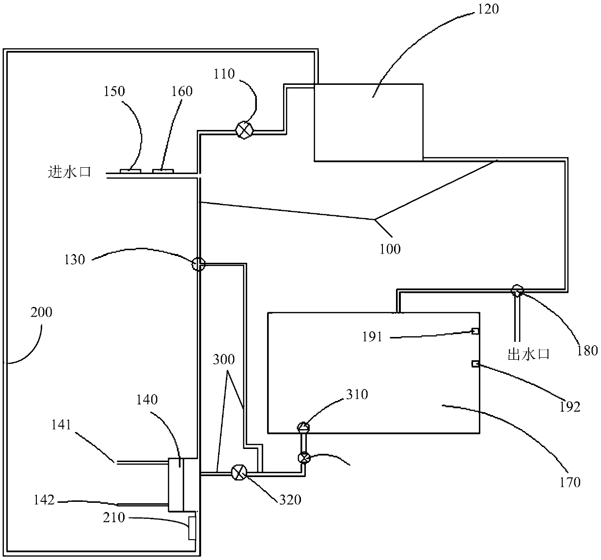
[0055] figure 1 It is a structural schematic diagram of a condensed water reuse system of a vehicle air-conditioning system according to an embodiment of the present invention, wherein the condensed water ...


PUM


Abstract

The invention relates to the technical field of vehicles and provides a vehicle air conditioning system and a condensate water recycling system thereof. The invention comprises a condensate water conveying pipeline. Condensate water flowing into the condensate water conveying pipeline flows to a first heat exchange device through a first electromagnetic valve to be subjected to heat exchange so asto reduce the temperature in a vehicle or flows to a second heat exchange device through a first outlet of a first three-way electromagnetic valve to be subjected to heat exchange so as to reduce thetemperature of condensate water; the condensate water feedback pipeline is communicated with the second heat exchange device and the first heat exchange device; the temperature detection device is used for detecting the temperature of condensate water; control device. Moreover, a control device is configured as follows: when the temperature of the condensate water is smaller than or equal to a set temperature threshold value, the first three-way electromagnetic valve and the first electromagnetic valve are controlled, so that the condensate water enters the first heat exchange device to be subjected to heat exchange and cooling, and otherwise, the condensate water enters the second heat exchange device to be subjected to heat exchange and then flows to the first heat exchange device through the condensate water feedback pipeline. The problem that heat exchange cannot be conducted due to insufficient temperature of condensate water is solved.

Description

technical field [0001] The invention relates to the technical field of vehicles, in particular to a vehicle air-conditioning system and a condensed water reuse system thereof. Background technique [0002] The vehicle air-conditioning system is a system that provides customers with functions such as cooling, heating, defrosting and defogging. When the air-conditioning system is cooling, the condenser often produces condensed water, which is then discharged out of the vehicle. Due to the low temperature of the condensed water (6°C-10°C), various schemes have been adopted in the prior art to re-use the condensed water to cool down other components of the thermal management of the vehicle, so as to improve the thermal management level of the vehicle the goal of. [0003] At present, there are mainly the following two condensed water secondary utilization schemes in the prior art: [0004] 1) Spray the condensed water of the air conditioner on the condenser of the air conditio...

Claims


Application Information

Patent Timeline
Patent Type & Authority Applications(China)
IPC IPC(8): B60H1/32
CPCB60H1/3233
Inventor 张骁诚
Owner GREAT WALL MOTOR CO LTD
Why Eureka
Try Eureka