
Multifunctional horizontal type automatic boxing machine

An automatic cartoning machine, multi-functional technology, applied in the directions of packaging, transportation and packaging, single objects, etc., can solve the problems of messy box body, increase the workload, affect customers' unpacking and use, and reduce the workload of workers. The effect of improving packing efficiency

Pending Publication Date: 2020-03-27
哈尔滨瀚钧现代制药有限公司
View PDF0 Cites 1 Cited by
  • Summary
  • Abstract
  • Description
  • Claims
  • Application Information

AI Technical Summary

Problems solved by technology

[0003] When the existing traditional automatic cartoning machine is ready to pack the cartons, the box body is very messy, which often requires manual operation by the staff, which increases the workload. The work efficiency of the automatic cartoning machine is low, and it may also cause the The front and back of the box body are reversed, which affects the use of customers out of the box

Method used


Image

  • Multifunctional horizontal type automatic boxing machine
  • Multifunctional horizontal type automatic boxing machine
  • Multifunctional horizontal type automatic boxing machine

Examples


Embodiment 1

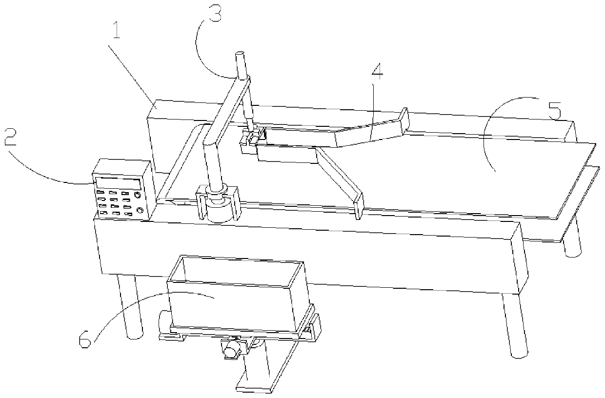
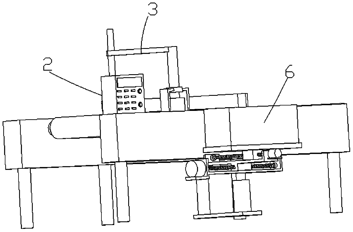
[0037]Such as figure 1 , 2 , 4 and 6, a multi-functional horizontal automatic cartoning machine, including a work frame 1, a controller 2 and a conveyor belt 5, the work frame 1 is connected to the conveyor belt 5 through the rotation of the rotating shaft, and the work frame 1 is symmetrically fixedly connected with a guide material Structure 4, material guide structure 4 includes straight plate 41, inclined plate 42 and connecting plate 43, connecting plate 43 is fixedly connected with inclined plate 42 for guiding, inclined plate 42 is fixedly connected with straight plate 41, connecting plate 43 is fixedly connected with working frame 1 , a controller 2 and a clamping structure 3 are fixed on the working frame 1, the controller 2 includes a control host, a display screen and an operation keyboard, the controller 2 is electrically connected to an external power supply, and the controller 2 is connected to the first electric push rod 35 respectively. , the second electric p...

Embodiment 2

[0039] Embodiment 2 is a further improvement on Embodiment 1.

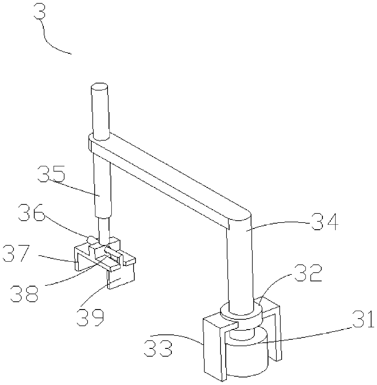
[0040] Such as figure 1 , 2 And 3, the clamping structure 3 includes a rotating motor 31, a support bearing 32, a support plate 33, an L-shaped plate 34, a first electric push rod 35, a second electric push rod 36 and an L-shaped splint 37, and the top of the L-shaped splint 37 is opened There are chute 38, T-shaped slide plate 39 and chute 38 sliding connection, support plate 33 and rotating motor 31 are all fixedly installed on the work frame 1, support plate 33 tops are fixedly connected with the outer ring of support bearing 32, support bearing 32 The inner ring is fixedly connected with the output end of the rotating motor 31 and the L-shaped plate 34. The L-shaped plate 34 is not in direct contact with the rotating motor 31, which can prolong the service life of the rotating motor 34. The lateral part of the L-shaped plate 34 is fixedly installed in the through hole There is a first electric push rod 35, a...

Embodiment 3

[0042] Embodiment three is a further improvement on embodiment two.

[0043] Such as figure 1 , 2 and 5, the bottom of the mounting frame 1 is provided with a practical box moving structure 6 that cooperates with the clamping structure 3, and the box moving structure 6 includes a horizontal plate 61, a first threaded rod 62, a first drive motor 63, a second threaded rod 64, box body 65, first slider 66, support frame 67, second drive motor 68, first U-shaped plate 69, second slider 610, hydraulic cylinder 611 and second U-shaped plate 612, on the horizontal plate 61 A hydraulic cylinder 611 is fixedly installed, and the telescopic end of the hydraulic cylinder 611 is fixedly connected with a first U-shaped plate 69, and the first U-shaped plate 69 is rotatably connected with a first threaded rod 62 through a fixedly connected bearing, and the first threaded rod 62 is connected to the first threaded rod 62. The output end of a driving motor 63 is fixedly connected, the first ...


PUM


Abstract

The invention relates to a multifunctional horizontal type automatic boxing machine in the technical field of boxing machines. The multifunctional horizontal type automatic boxing machine comprises aworking frame, wherein the working frame is provided with a conveying belt and a material guiding structure; the material guiding structure comprises a straight plate, an inclined plate and a connecting plate; the connecting plate is connected with the inclined plate; the inclined plate is connected with the straight plate; a controller and a clamping structure are arranged on the working frame; the clamping structure comprises a rotating motor, a supporting bearing, a supporting plate, an L-shaped plate, a first electric push rod, a second electric push rod and an L-shaped clamping plate; thesupporting plate is connected with the supporting bearing; the supporting bearing is connected with the rotating motor and the L-shaped plate; a first electric push rod is arranged on the L-shaped plate; the first electric push rod is connected with the L-shaped clamping plate; the first electric push rod is provided with the second electric push rod; the second electric push rod is connected with a T-shaped sliding plate; and the working frame is provided with a box body moving structure. Through mounting the material guiding structure on the working frame, the inclined plate in the materialguiding structure corrects medicine boxes on the conveying belt, then the medicine boxes are guided by means of the straight plate and adjusted to positions where the clamping structure can clamp themedicine boxes conveniently, and the boxing efficiency is improved.

Description

technical field [0001] The invention relates to the technical field of cartoning machines, in particular to a multifunctional horizontal automatic cartoning machine. Background technique [0002] Packaging machinery refers to machinery that can complete all or part of the product and commodity packaging process. The packaging process includes main processes such as filling, wrapping, and sealing, as well as related pre- and post-processing processes, such as cleaning, stacking, and disassembly. Packaging also includes processes such as metering or stamping on packages. The use of mechanical packaging products can increase productivity, reduce labor intensity, meet the needs of large-scale production, and meet the requirements of cleanliness and sanitation. Cartoning machine is a kind of packaging machinery, including automatic cartoning machine, medicinal cartoning machine and so on. The automatic cartoning machine is to automatically pack medicine bottles, medicine board...

Claims


Application Information

Patent Timeline
IPC IPC(8): B65B5/08B65B35/24B65B35/56B65B35/16
CPCB65B5/08B65B35/16B65B35/24B65B35/56
Inventor 贾德君韩姗姗
Owner 哈尔滨瀚钧现代制药有限公司
Learn More