Integrated valve for tunnel construction

A technology of tunnel construction and integrated valves, which is applied in tunnels, tunnel linings, valve details, etc., can solve the problems of material backflow into air ducts, nozzle vibration, difficult accelerators, etc., and achieve the effect of uniform wind diffusion

Active Publication Date: 2020-03-27
RAILWAY NO 5 BUREAU GRP FIRST ENG CO LTD
View PDF7 Cites 2 Cited by
  • Summary
  • Abstract
  • Description
  • Claims
  • Application Information

AI Technical Summary

Problems solved by technology

[0004] 1. The concrete pipes, accelerator pipes, and air pressure pipes in the prior art interact with each other when working together, resulting in jitter, which causes the pressure at the nozzle to jitter, so that the spraying is uneven and not in place, and in severe cases, the nozzle will jitter
[0005] 2. When the concrete pipes, quick-setting agent pipes, and air pressure pipes of the prior art work together, the pipes are scattered or fixed separately. When they are fixed separately, there is a problem that it is difficult to take into account the matching distance and the fixed distance.
[0006] 3. The concrete delivery pipeline of the prior art has the problem that it is difficult to fully integrate with the accelerator, or although it is integrated, a specific structure is required to realize it, which increases the cost
[0007] 4. The air duct in the prior art is not uniform enough in air supply, which indirectly leads to uneven spraying of materials
[0008] 5. In the air duct of the prior art, when the internal pressure of the injection failure increases, it is easy to cause the material to flow back into the air duct, pollute and damage the air duct
[0009] 6. When spraying in the prior art, when the internal pressure of the spraying fault increases, it is easy to cause damage to the confluence pipeline
[0010] 7. The unloading valves in the prior art are often simple in structure and poor in adaptability. They are only simple one-way valves and cannot adapt to complex working conditions.

Method used


Image

  • Integrated valve for tunnel construction
  • Integrated valve for tunnel construction
  • Integrated valve for tunnel construction

Examples


Embodiment Construction

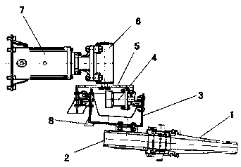
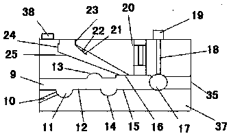
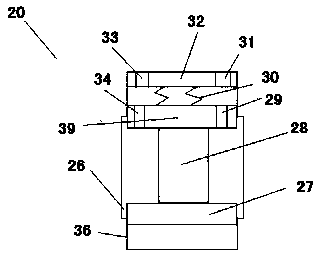
[0038] As shown in the figure: an integrated valve for tunnel construction, including concrete inlet, accelerator inlet, mixing part, diameter shrinkage part, diameter expansion part, direction change part, confluence pipe, buffer convex cavity, valve core, valve stem, Valve driver, pressure relief valve, air valve plate, bump, air duct connection port, air duct sinking part, inclined air duct, integrated valve outlet, integrated block body, integrated block connector; the pressure relief valve includes the following Piston, piston rod, upper piston, upper piston hole, spring, bonnet, bonnet hole, pressure relief valve cavity, expansion cavity;

[0039] As shown in the figure: the concrete inlet is set below the centerline of the left wall of the integrated block, the accelerator inlet is arranged below the concrete inlet, the right end of the concrete inlet is connected to the mixing part, and the upper end of the mixing part is flush with the upper end of the concrete inlet. ...


PUM


Abstract

An integrated valve for tunnel construction comprises a concrete inlet, an accelerator inlet, a mixing part, a reducing part, an expanding part, a turning part, a converging pipe, a buffering convex cavity, a valve element, a valve rod, a valve driving part, a pressure relief valve, an air valve plate, a convex block, an air duct connecting port, an air duct sinking part, an inclined air duct, anintegrated valve outlet, an integrated block body and an integrated block connecting part. The pressure relief valve comprises a lower piston, a piston rod, an upper piston, an upper piston hole, a spring, a valve bonnet, a valve bonnet hole, a pressure relief valve cavity and an expanding cavity. The concrete inlet is formed in the position below the center line of the left wall of the integratedblock body, the accelerator inlet is formed below the concrete inlet, the right end of the concrete inlet is communicated with the mixing part, the upper end of the mixing part is aligned with the upper end of the concrete inlet, the lower end of the mixing part protrudes downwards relative to the lower end of the concrete inlet, and the protruding part is communicated with the accelerator inlet.

Description

technical field [0001] The invention relates to the field of tunnel construction, in particular to an integrated valve for tunnel construction. Background technique [0002] In the construction process of domestic mine roadways, railway and highway tunnels, water conservancy culverts, various underground projects, high-rise building foundation pits, military projects, etc., the international advanced shotcrete anchor support construction method is widely used in the early stage support. Concrete (concrete) spraying machine is the main equipment of this operation and plays a vital role. Concrete spraying machine is usually divided into three types: dry spraying machine, tidal spraying machine and wet spraying machine. [0003] In the actual use of the wet spray machine, there are the following problems: [0004] 1. The concrete pipes, accelerator pipes, and air pressure pipes in the prior art interact with each other when working together, resulting in jitter, which causes t...

Claims


Application Information

Patent Timeline
Patent Type & Authority Applications(China)
IPC IPC(8): F16K11/20F16K31/04F16K27/00E21D11/10
CPCE21D11/10F16K11/20F16K27/00F16K31/04
Inventor 曹振兴朱胥仁彭学军陈彬吴彪杨文国汤宇李传书苗永旺杨俊峰杨曾罗朝华胥俊伟李一萍胡从文范方贵凌涛邓满林
Owner RAILWAY NO 5 BUREAU GRP FIRST ENG CO LTD
Why Eureka
Try Eureka