Trigger device, trigger system and trigger method of pneumatic net gun of unmanned aerial vehicle

A technology of triggering device and unmanned aerial vehicle, which is applied to unmanned aerial vehicles, motor vehicles, compressed air guns, etc., can solve the problems of large volume of triggering device, large influence of ambient temperature, complicated operation, etc., and achieves light weight and reliability. High, small size effect

Active Publication Date: 2020-03-27
BEIJING MECHANICAL EQUIP INST
View PDF4 Cites 1 Cited by
  • Summary
  • Abstract
  • Description
  • Claims
  • Application Information

AI Technical Summary

Problems solved by technology

[0006] In view of the above analysis, the present invention aims to provide a triggering device, a triggering system and a triggering method for a pneumatic net gun of an unmanned aerial vehicle, in order to solve the problem that the triggering device in the prior art is large in size, heavy in weight, complex in structure, complex in operation, and greatly affected by ambient temperature. And other issues

Method used


Image

  • Trigger device, trigger system and trigger method of pneumatic net gun of unmanned aerial vehicle
  • Trigger device, trigger system and trigger method of pneumatic net gun of unmanned aerial vehicle
  • Trigger device, trigger system and trigger method of pneumatic net gun of unmanned aerial vehicle

Examples


Embodiment 1

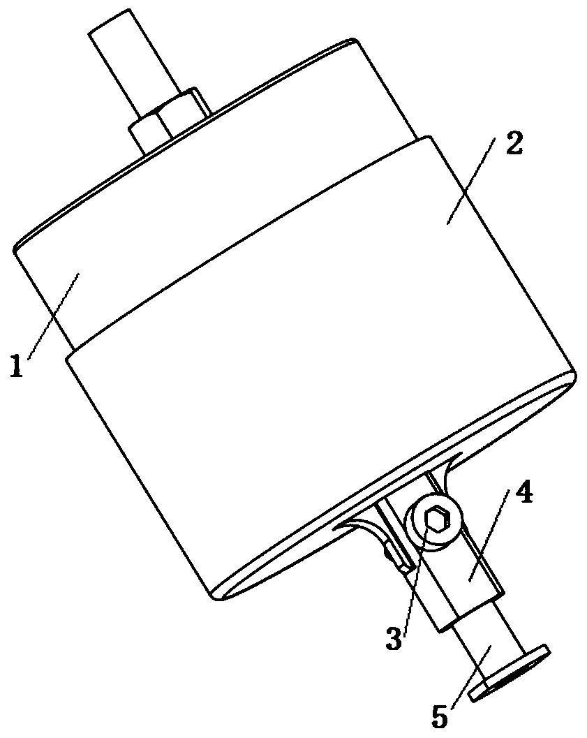
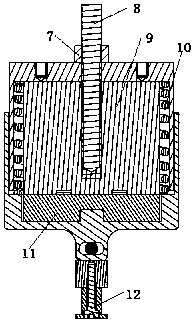
[0046] A specific embodiment of the present invention, such as Figure 1-Figure 4 As shown, a pneumatic net gun trigger device includes a top cover 1 , a bottom cover 2 , a de-energized electromagnet 9 , a suction cup 11 and a spring 10 . The de-energized electromagnet 9 is arranged in the top cover 1 , the suction cup 11 is arranged in the bottom cover 2 , and the spring 10 is compressed in the top cover 1 by the suction of the de-energized electromagnet 9 and the suction cup 11 . The spring 10 is used to apply elastic force to the bottom cover 2 to eject the bottom cover 2, so that the bottom cover 2 applies a trigger force to the pneumatic net gun 17.

[0047]Pneumatic net gun trigger device suction cup 11 is a cast iron material, and all the other part materials are aluminum alloys. Lost power type electromagnet 9 has magnetic force when not applying voltage at ordinary times, and magnetic force disappears when applying 24V voltage. Lost power type electromagnet 9 also c...

Embodiment 2

[0080] A pneumatic net gun trigger system such as Figure 5 , Figure 6 As shown, it includes the pneumatic net trigger device in Embodiment 1, and also includes an upper clamp 16 and a lower clamp 18; The clamps 18 are connected, and the pneumatic net gun 17 is clamped in the circular hole formed by the upper clamp 16 and the lower clamp 18 .

[0081] The upper clamp 16 is provided with a rectangular groove and a first semicircular groove, and the pneumatic net gun trigger device is arranged in the rectangular groove.

[0082] The center position of the top of the rectangular groove of the upper fixture 16 protrudes upwards to form a raised bar 1601. The center of the raised bar 1601 is provided with a first opening 1602. The upper end of the stud 8 passes through the first opening 1602, and passes through the stud 8 and the third The nut 15 installs the trigger device in the rectangular groove; the second nut 7 of the trigger device enters the protruding strip 1601, so tha...

Embodiment 3

[0087] A triggering method of a pneumatic net gun adopts the trigger system of a pneumatic net gun in embodiment 2, comprising the following steps:

[0088] Step 1. Install the trigger device;

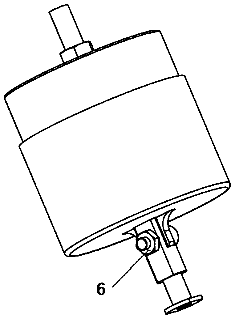
[0089] Remove the trigger seat 5 from the trigger link 4, then remove the trigger link 4 from the bottom cover 2, and then fix the trigger device with the removed trigger link 4 and trigger seat 5 in the rectangular groove: stud 8 The upper end passes through the first opening 1602, the second nut 7 of the trigger device enters the protruding strip 1601, and the trigger device is installed in the rectangular groove through the stud 8 and the third nut 15; the fourth screw 14 passes through the second opening The hole 1603 is screwed into the threaded hole provided on the bottom surface of the top cover 1 to further fix the trigger device. Then use the first screw 3 and the first nut 6 to install the trigger link 4 on the bottom cover 2, finally pass the trigger seat 5 through the throug...


PUM


Abstract

The invention discloses a trigger device, trigger system and trigger method of a pneumatic net gun of an unmanned aerial vehicle, and belongs to the technical field of pneumatic net gun triggering ofunmanned aerial vehicles. The trigger device, trigger system and trigger method of the pneumatic net gun of the unmanned aerial vehicle are used for solving the problems in the prior art, such as large volume, heavy weight, complex structure, complex operation, large influence by the ambient temperature, etc.. The trigger device of the pneumatic net gun comprises a top cover (1), a bottom cover (2), a first sucking part, a second sucking part and an elastic part; the first sucking part is fixed to the inner part of the top cover (1), the second sucking part is fixed to the inner part of the bottom cover (2), the elastic part is compressed in the top cover (1) through sucking of the first sucking part and the second sucking part, the elastic part is used for applying the elastic force to the bottom cover (2) to eject the bottom cover (2), and thus the bottom cover (2) exerts the triggering force to the pneumatic net gun (17). The trigger device, trigger system and trigger method of thepneumatic net gun of the unmanned aerial vehicle are suitable for triggering of the pneumatic net gun of the unmanned aerial vehicle.

Description

technical field [0001] The invention belongs to the technical field of triggering a pneumatic net gun of an unmanned aerial vehicle, and in particular relates to a triggering device, a trigger system and a trigger method for a pneumatic net gun of an unmanned aerial vehicle. Background technique [0002] The pneumatic net gun that guides the UAV is powered by a high-pressure gas cylinder, and the flexible net is thrown out by pressing the button on the pneumatic net gun to release the high-pressure gas from the cylinder. [0003] At present, there are manual and automatic ways to press the button on the pneumatic net gun. The manual way is to press the button by hand; the automatic way is mainly driven by the motor and the steering gear to drive the trigger lever to press the button down. [0004] The manual method can only be pressed on the ground when the air net gun has not been installed on the UAV. Once the air net gun is installed on the UAV or the UAV takes off, it is...

Claims


Application Information

Patent Timeline
Patent Type & Authority Applications(China)
IPC IPC(8): F41B11/70F41B11/80B64D7/02
CPCF41B11/70F41B11/80B64D7/02B64U2101/00
Inventor 李雪初巴腾跃彭延云李大伟
Owner BEIJING MECHANICAL EQUIP INST
Why Eureka
Try Eureka