Aero-engine electrical system line automatic detection device

An automatic detection device, aero-engine technology, applied in the direction of engine test, measurement device, short-circuit test, etc., can solve the problems of increasing the size and weight of the test system, switching noise, and bulky, saving labor costs and time costs. , Easy to use, simple and compact structure

Active Publication Date: 2020-03-27
AECC SICHUAN GAS TURBINE RES INST
View PDF4 Cites 1 Cited by
  • Summary
  • Abstract
  • Description
  • Claims
  • Application Information

AI Technical Summary

Problems solved by technology

[0005] 1) The function is relatively simple. Some instruments have the functions of point-to-point continuity, insulation and voltage resistance detection of cables, but they often do not have the functions of cable connection correspondence, resistance detection and switch value detection of airborne accessories. , unable to fully meet the requirements of the inspection procedure before the aero-engine test;
[0006] 2) In special fields such as aero-engines, high-precision and high-reliability detection devices are required. However, detection devices using electronic analog switches on the market have relatively large on-resistance, generally ranging from a few ohms to tens of ohms, which introduces measurement errors; And the integrated multi-channel analog switch has limited working voltage, which is not suitable for insulation and withstand voltage testing;
[0007] 3) On the other hand, due to the large amount of test data (usually the number of cables is as many as hundreds of cores), the equipment using the relay array is bulky, which increases the size and weight of the test system, and secondly, the relay needs to drive the circuit, which will increase the circuit. The complexity reduces the reliability of the system; moreover, when the relay is working, it is caused by switching noise and high power consumption

Method used


Image

  • Aero-engine electrical system line automatic detection device
  • Aero-engine electrical system line automatic detection device
  • Aero-engine electrical system line automatic detection device

Examples


Embodiment Construction

[0059] According to the attached Figure 1-11 To further describe the present invention,

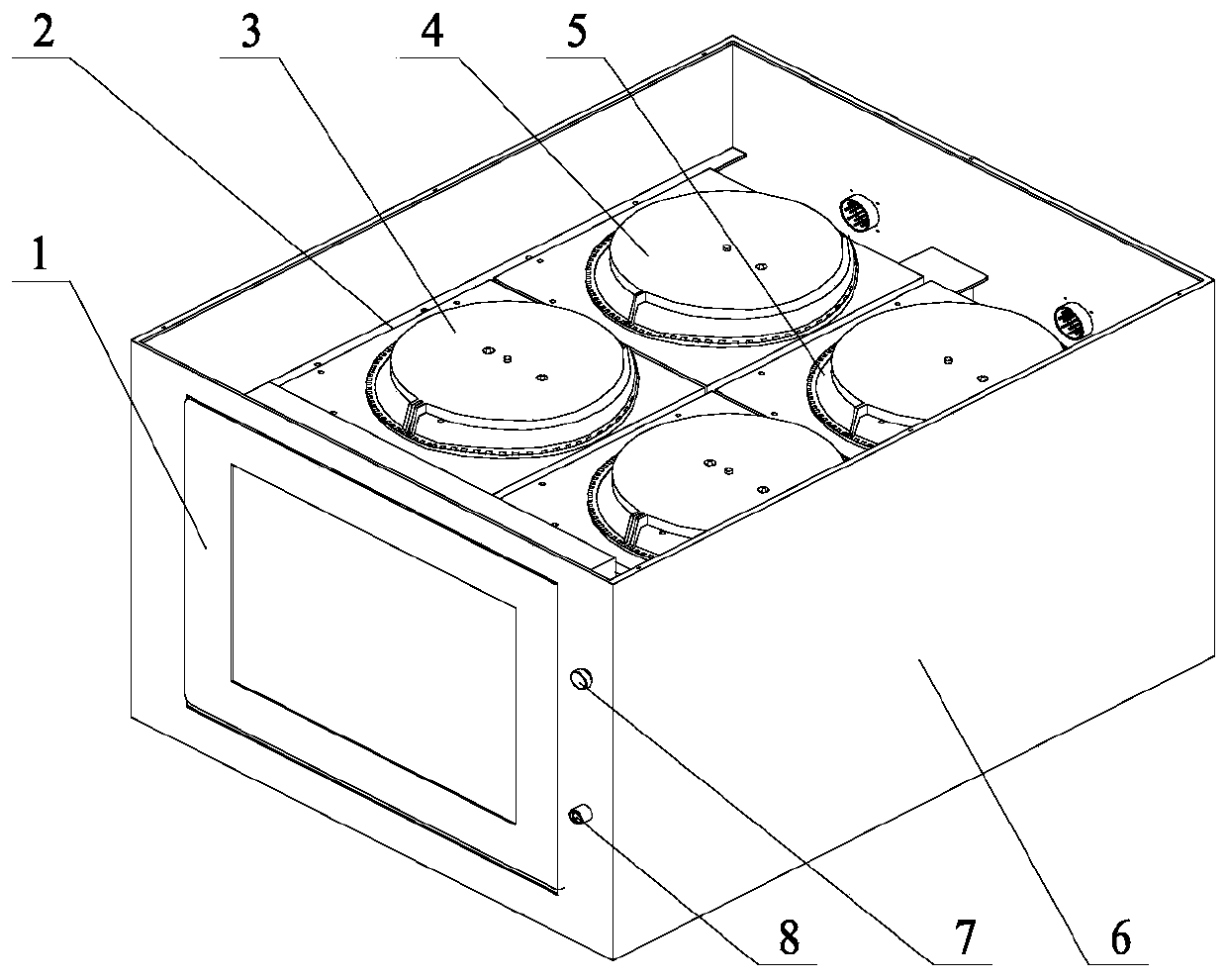
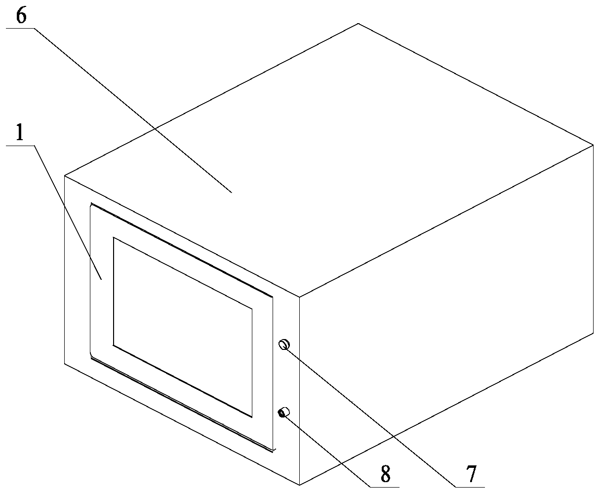
[0060] Such as Figure 1-8 As shown, it is a schematic structural diagram of the automatic detection device provided by the present invention. The device provided by the present invention includes a detection mechanical component, a main control component and a detection circuit component,

[0061] The detection mechanical parts include a casing (6), the casing (6) is hollow, and two unipolar multi-channel mechanical switches (3) and two bipolar multi-channel mechanical switches (4) are arranged inside the casing (6). The unipolar multi-channel mechanical switch (3) and the bipolar multi-channel mechanical switch (4) are fixed on the bracket (2) arranged in the casing (6);

[0062] The front panel of the housing (6) is provided with a touch screen integrated machine (1), a power button (7) and a power indicator light (8);

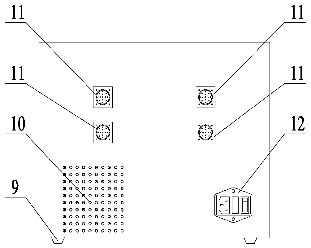
[0063] The rear panel of the casing (6) is provided with a fa...


PUM


Abstract

The invention provides an aero-engine electrical system line automatic detection device. The device comprises a detection mechanical part, a main control part and a detection circuit part; the detection mechanical part comprises a shell (6), the shell (6) is hollow, two single-pole multi-way mechanical switches (3) and two double-pole multi-way mechanical switches (4) are arranged in the shell (6), and the single-pole multi-way mechanical switches (3) and the double-pole multi-way mechanical switches (4) are fixed to a support (2) arranged in the shell (6). According to the aero-engine electrical circuit automatic detection device, a reasonable mechanical automatic switch is designed, the structure is simple and compact, and a multifunctional automatic detection circuit is designed in combination with electrical system detection experience. Automatic detection of an electrical system on the aero-engine test bed can be realized, good test precision and test efficiency can be ensured, and the application effect in aero-engine tests is good.

Description

technical field [0001] The invention belongs to the field of aero-engine testing, and in particular relates to an automatic detection device for electrical system circuits of an aero-engine Background technique [0002] With the advancement of technology, the aero-engine control system has developed into an ESC and full-authority digital control system, and its electrical accessories and circuits have gradually increased. The aeroengine electrical system circuit is a neural network that connects controllers, onboard sensors / electrical accessories, and control systems to provide power, control signals, and data information for each component of the engine. Through certain technical means to detect the electrical system circuit, most of the electrical logic faults of the bench electrical and engine accessory equipment can be found in advance. Therefore, the key link of aeroengine electrical system circuit detection has been highly valued by all parties. [0003] At present, ...

Claims


Application Information

Patent Timeline
IPC IPC(8): G01M15/00G01R31/56G01R31/54G01R31/52G01R31/12G01R31/00
CPCG01M15/00G01R31/00G01R31/12
Inventor 彭晋雷勇郑逯文徐红章张湘军张志林
Owner AECC SICHUAN GAS TURBINE RES INST
Why Eureka
Try Eureka