Eutectic welding machine for die bonding of LED chip and working method thereof

A LED chip and eutectic soldering technology, which is applied in the direction of electrical solid devices, semiconductor/solid device manufacturing, electrical components, etc., can solve the problems of low efficiency of chip glue coating, inaccurate chip position, and chip shedding, etc., to achieve consistent thickness , welding is convenient, and the effect of ensuring accuracy

Inactive Publication Date: 2020-03-27
马鞍山三投光电科技有限公司
View PDF6 Cites 0 Cited by
  • Summary
  • Abstract
  • Description
  • Claims
  • Application Information

AI Technical Summary

Problems solved by technology

[0004] The object of the present invention is to provide a kind of eutectic welding machine and its working method for LED chip bonding, which can solve the problem that the existing chip eutectic welding machine has a simple structure, and the chip is usually fixed and installed manually, and the chip installation process is easy. The location of the occurrence is not accurate enough, and the use after installation is affected
Due to the uneven application of glue and the low efficiency of the glue application method of the chip, the chip is easy to fall off after soldering, which is a technical problem with large limitations.

Method used


Image

  • Eutectic welding machine for die bonding of LED chip and working method thereof
  • Eutectic welding machine for die bonding of LED chip and working method thereof
  • Eutectic welding machine for die bonding of LED chip and working method thereof

Examples


Embodiment Construction

[0032] The technical solutions of the present invention will be clearly and completely described below in conjunction with the embodiments. Apparently, the described embodiments are only some of the embodiments of the present invention, not all of them. Based on the embodiments of the present invention, all other embodiments obtained by persons of ordinary skill in the art without creative efforts fall within the protection scope of the present invention.

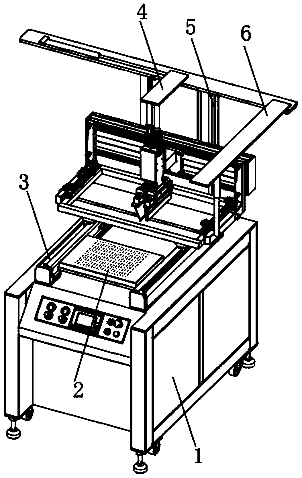
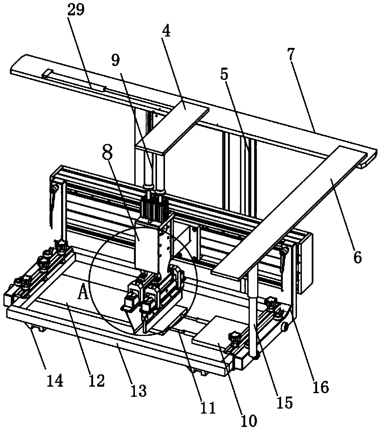
[0033] see Figure 1-7 As shown, a eutectic welding machine for LED chip solidification includes a base 1 and a welding mechanism, and the welding mechanism is slidably installed on the upper part of the base 1;

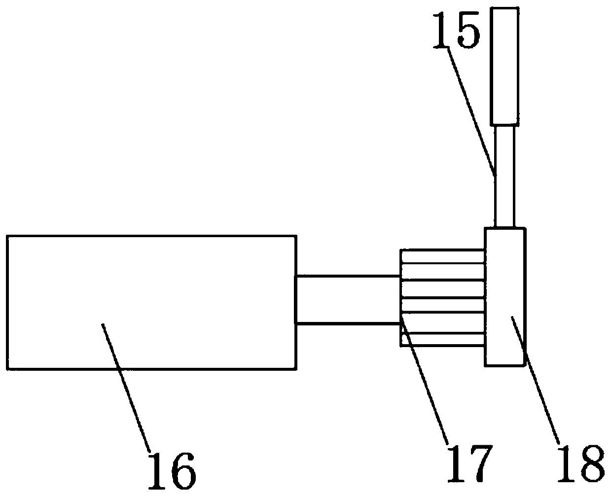
[0034] The welding mechanism includes a load-bearing plate 26, side plates 16 are movably connected to both sides of the top of the load-bearing plate 26, and the opposite sides of the two side plates 16 are horizontally connected to the first end plate 10 and the second end plate 12 respectively. , a second elec...


PUM


Abstract

The invention discloses a eutectic welding machine for die bonding of an LED chip. The eutectic welding machine comprises a base and a welding mechanism, wherein the welding mechanism is installed onthe upper portion of the base in a sliding mode; the welding mechanism comprises a bearing plate; side plates are movably connected to the two sides of the top of the bearing plate; and the opposite sides of the two side plates are horizontally connected with a first end plate and a second end plate correspondingly, and a second electric telescopic column is horizontally installed between the first end plate and the second end plate. Welding is more convenient, and cleanness and sanitation during installation can be kept under the condition that the chip is firmly installed, and the quality offollow-up use of the chip is not prone to being affected. In the glue smearing process, redundant glue overflows from the two sides of the upper portion of the chip to flow onto the bearing plate, and the redundant glue is not prone to being accumulated on the upper portion of the chip, thus guaranteeing that the chip can be used safely and efficiently.

Description

technical field [0001] The invention relates to a eutectic welding machine, in particular to a eutectic welding machine for solid crystal of LED chips and a working method thereof, belonging to the field of chip installation applications. Background technique [0002] Chip, also known as microcircuit. Refers to silicon chips containing integrated circuits, which are small in size and are often part of computers or other electronic equipment. The chip is often installed and fixed on the circuit board by a eutectic soldering machine. [0003] But the existing chip eutectic welding machine still has certain deficiencies in use. The existing chip eutectic welding machine has a simple structure, and the chip is often fixed and installed manually. During the chip installation process, the position is prone to be inaccurate, and the use after installation is affected. During the eutectic soldering process, the amount of glue is not easy to control, and the glue at the end of the...

Claims


Application Information

Patent Timeline
IPC IPC(8): H01L21/67H01L33/62H01L21/60
CPCH01L21/67144H01L24/75H01L33/62H01L2224/75
Inventor 张文具刘晓旭
Owner 马鞍山三投光电科技有限公司
Why Eureka
Try Eureka