Intelligent cooling device for power high-voltage switch cabinet and using method thereof
What is Al technical title?
Al technical title is built by PatSnap Al team. It summarizes the technical point description of the patent document.
A technology of high-voltage switchgear and cooling device, which is applied to the cooling/ventilation of substation/switchgear, board/panel/desk of substation/switchgear, and layout details of substation/switch, etc., can solve the slow temperature control effect and difficult installation , different sizes of electrical switches, etc., to achieve the effect of improving work efficiency, avoiding fire accidents, and fast temperature control.
Inactive Publication Date: 2020-03-27
STATE GRID SHANDONG ELECTRIC POWER +1
View PDF4 Cites 6 Cited by
Summary
Abstract
Description
Claims
Application Information
AI Technical Summary
This helps you quickly interpret patents by identifying the three key elements:
Problems solved by technology
Method used
Benefits of technology
Problems solved by technology
[0003] At present, most of the existing cooling devices for electric high-voltage switchgear adopt the method of artificial cooling. Due to the long-term operation of the high-voltage cabinet, the cost of manual cooling is high, and the temperature control effect is slow, which reduces the working efficiency of the high-voltage switchgear. Installing an automatic fire extinguisher is likely to cause fire accidents and cannot meet the needs of the high-voltage switchgear cooling device. Secondly, because most of the interior adopts a fixed structure, the size of the electrical switch is different, the installation is difficult, and the fixing is inconvenient, which affects the installation of the high-voltage switchgear cooling device. efficiency
Method used
Image
Click on the blue label to locate the original text in one second.
Reading with bidirectional positioning of images and text.
Examples
Embodiment Construction
[0035] The present invention will be further described below in conjunction with accompanying drawing:
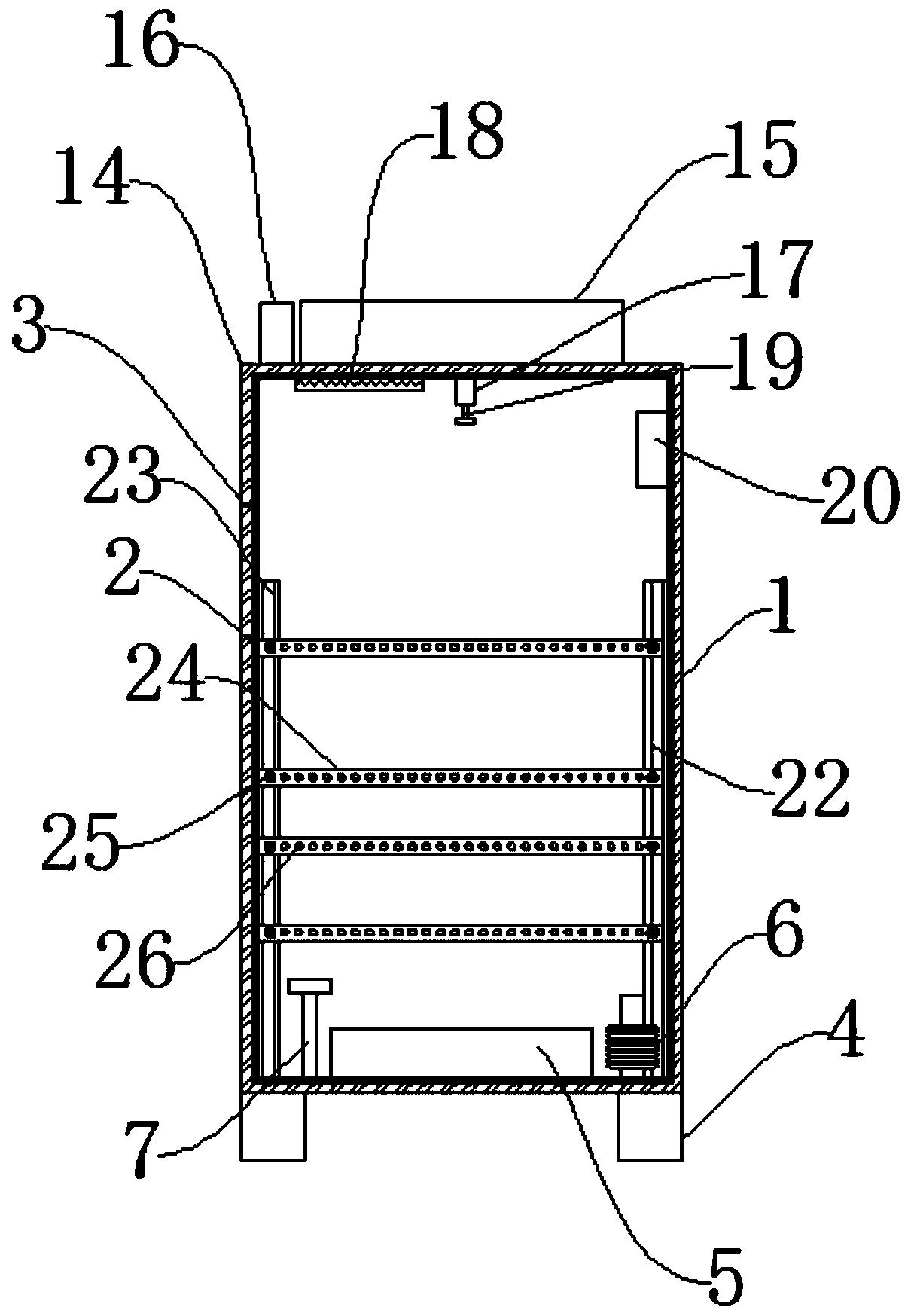
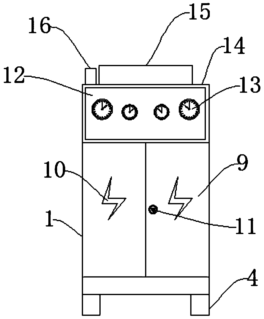
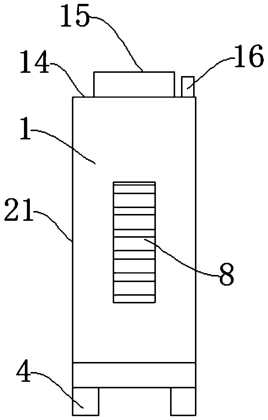
[0036] Such as Figure 1-Figure 5 As shown, an intelligent cooling device for electric high-voltage switchgear includes a cabinet body 1, a lightning arrester 6, a dry powder fire extinguisher 15, and a ground rod 7. One side of the cabinet body 1 is provided with a thermal insulation board 2, and one side of the thermal insulation board 2 is provided with an insulating inner panel. 3. Through the insulating inner plate 3, the switchgear can prevent electric leakage. A base 4 is installed under the insulating inner plate 3. A cooling fan 5 is installed in the middle above the base 4. A lightning arrester 6 is installed on one side of the cooling fan 5, and an arrester 6 is installed on the other side of the cooling fan 5. A grounding rod 7 is provided, and heat dissipation windows 8 are provided on both sides of the cabinet body 1, and a cabinet door 9 is provided on the ad...
PUM
Abstract
The invention discloses an intelligent cooling device for an electric power high-voltage switch cabinet and a use method thereof, the intelligent cooling device comprises a cabinet body, a lightning arrester, a dry powder extinguisher and a grounding rod, and one side of the cabinet body is provided with an insulation board. Beneficial effects are as follows: the intelligent temperature controller, the cooling fan and the insulation board are arranged, automatic cooling can be realized in the switch cabinet; normal operation of high-voltage switch cabinet is realized, cost is saved, temperature control effect is fast, the working efficiency of the high-voltage switch cabinet is improved; and as the dry powder extinguisher, a spray pipe, a smoke sensing head and an alarm are arranged, electrical components in the high-voltage power distribution cabinet can be burnt down to automatically extinguish fire, thus fire accidents can be avoided, and people can be reminded to leave a dangerousarea, the device meets the use requirements of the high-voltage switch cabinet cooling device, electric appliance switches of different sizes can be arranged by arranging the first sliding strip, thesecond sliding strip, the fixing plate, the locking screws and the installation holes, electric switches of different sizes can be installed, the installation is convenient and rapid, and fixed and stable, and the installation efficiency of the high-voltage switch cabinet cooling device is enhanced.
Description
technical field [0001] The invention relates to the technical field of high-voltage switch cabinets, in particular to an intelligent cooling device for electric high-voltage switch cabinets and a method for using the same. Background technique [0002] High-voltage switchgear refers to the role of on-off, control or protection in power system power generation, transmission, distribution, power conversion and consumption. High-voltage switchgear is used as electrical products with a voltage level of 3.6kV~550kV, and high-voltage isolating switches And grounding switch, high-voltage load switch, high-voltage automatic recloser and sectionalizer, high-voltage operating mechanism, high-voltage explosion-proof power distribution device and high-voltage switchgear and other major categories. [0003] At present, most of the existing cooling devices for electric high-voltage switchgear adopt the method of manual cooling. Due to the long-term operation of the high-voltage cabinet, t...
Claims
Application Information
Patent Timeline
Application Date:The date an application was filed.
Publication Date:The date a patent or application was officially published.
First Publication Date:The earliest publication date of a patent with the same application number.
Issue Date:Publication date of the patent grant document.
PCT Entry Date:The Entry date of PCT National Phase.
Estimated Expiry Date:The statutory expiry date of a patent right according to the Patent Law, and it is the longest term of protection that the patent right can achieve without the termination of the patent right due to other reasons(Term extension factor has been taken into account ).
Invalid Date:Actual expiry date is based on effective date or publication date of legal transaction data of invalid patent.