
Claw pole for hybrid excitation generator and hot forging finishing manufacturing process thereof

A hybrid excitation and manufacturing process technology, applied in the manufacture of motor generators, stator/rotor bodies, electric components, etc., can solve the problem of high requirements for workers to operate, and achieve the effect of improving processing accuracy

Active Publication Date: 2020-03-27
浙江昕博汽车零部件制造有限公司
View PDF3 Cites 0 Cited by
  • Summary
  • Abstract
  • Description
  • Claims
  • Application Information

AI Technical Summary

Problems solved by technology

[0005] The above-mentioned prior art has the following defects. When installing, the magnet must be installed in the magnet installation groove of one claw pole before installing another claw pole. When installing the last claw pole, the magnet of the last claw pole must be The installation can only be assembled after the installation groove is aligned with the installed magnet, which requires a high level of operation for workers

Method used


Image

  • Claw pole for hybrid excitation generator and hot forging finishing manufacturing process thereof
  • Claw pole for hybrid excitation generator and hot forging finishing manufacturing process thereof
  • Claw pole for hybrid excitation generator and hot forging finishing manufacturing process thereof

Examples


Embodiment 1

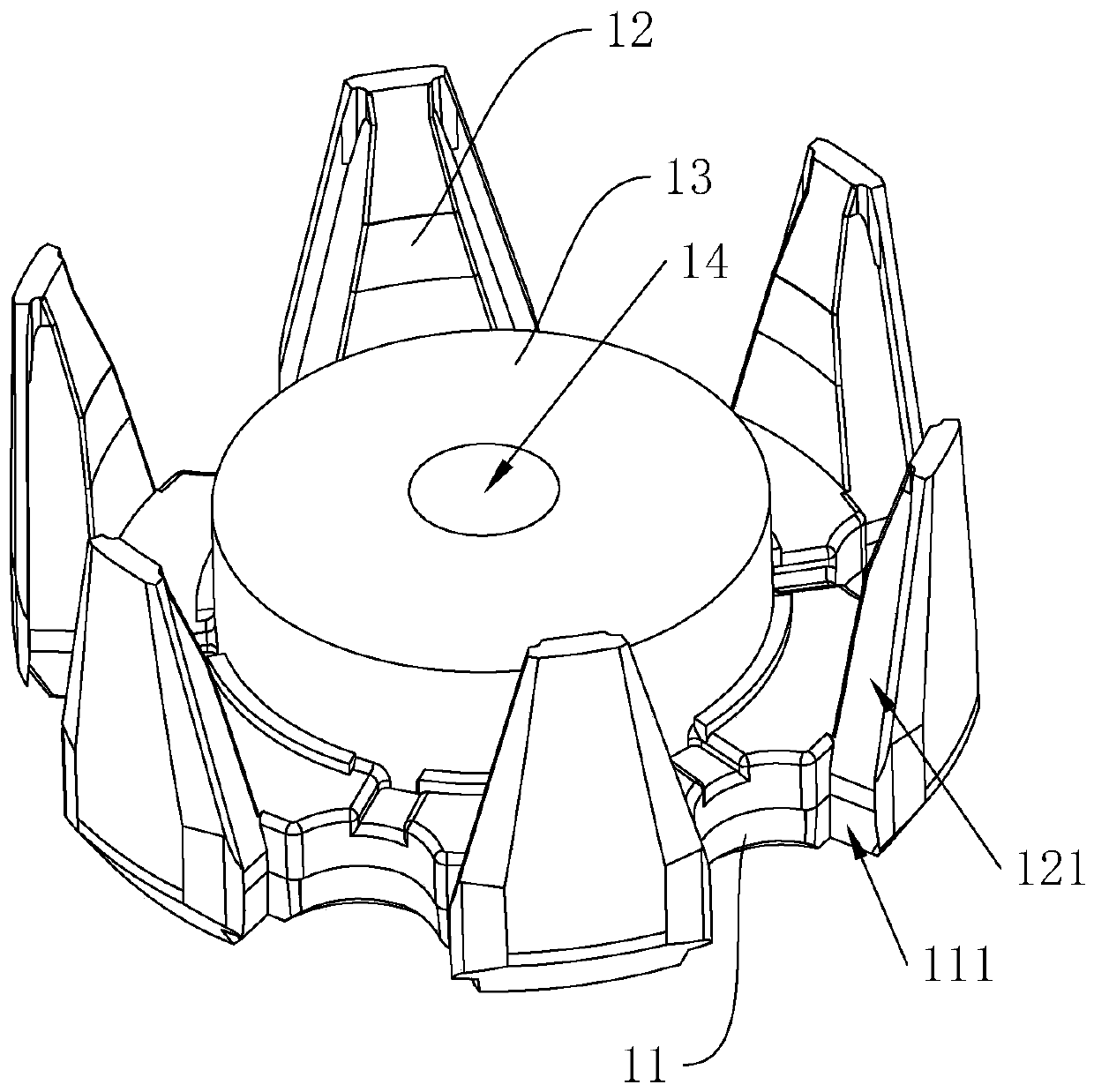
[0051] A claw pole for hybrid excitation generator, refer to figure 1 , Including an integrated bottom plate 11, a claw ruler 12 and a magnetic yoke 13. The two side walls of the claw ruler 12 are provided with magnet mounting slots 121. One end of the magnet mounting groove 121 extends to the butt of the claw ruler 12 and the bottom plate 11, and the other end Through the claw ruler 12, the claw ruler 12 gradually narrows away from the base. The bottom plate 11 is provided with a sliding groove 111 communicating with the magnet installation groove 121 for the magnet to slide in.

[0052] When in use, first connect the claw pole of the present application with the existing claw pole, and then slide the magnet into the sliding groove 111 of the claw pole of the present application. After the magnet abuts against the base of the other claw pole, the magnet is completed. Install, and then locate the magnet through wax seal.

Embodiment 2

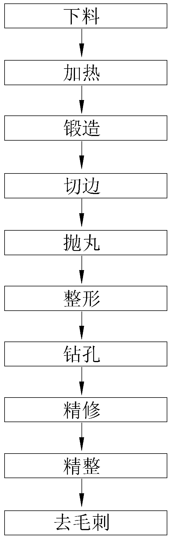
[0054] A claw pole hot forging and finishing manufacturing process for hybrid excitation generators is used to manufacture the claw poles described in the first embodiment, refer to figure 2 , Including the following specific steps:

[0055] S1. Cutting, cutting the cylindrical long embryo into several sections of originals to be processed through the cutting machine, wherein the ratio of the height to the diameter of the originals after cutting is less than 2.

[0056] S2, heating, heating the original part through an intermediate frequency furnace to facilitate subsequent forging.

[0057] S3. Forging, forging the heated original parts through a press and processing the finished products.

[0058] S3 specifically includes: S3.1, upsetting, the heated original is squeezed through a punching machine to reduce the height and increase the cross section, while removing the surface oxide scale; S3.2, rough forging, through 630T friction The press performs preliminary forging on the upset...


PUM


Abstract

The invention discloses a claw pole for a hybrid excitation generator and a hot forging finishing manufacturing process thereof and relates to the technical field of claw pole production. The problemin the prior art that operation is complicated because of assembly of magnets and claw poles is solved. . Key points of the technical scheme are as follows: the pole comprises a bottom plate, a clawruler and a magnet yoke which are integrally arranged, magnet mounting grooves are formed in the two side walls of the claw ruler, one ends of the magnet mounting grooves extend to the butt joint position of the claw ruler and the bottom plate, the other ends of the magnet mounting grooves penetrate out of the claw ruler, the claw ruler is gradually narrowed in the direction away from the base, and sliding grooves communicating with the magnet mounting grooves and used for allowing magnets to slide in are formed in the bottom plate. The claw pole can be butted firstly, and then the magnets aremounted, so that the overall assembly is facilitated.

Description

Technical field [0001] The invention relates to the technical field of claw pole production, in particular to a claw pole hot forging and finishing manufacturing process for a hybrid excitation generator. Background technique [0002] Hybrid excitation generator is a kind of high-power and lightweight generator. Compared with ordinary generators, it is different from ordinary generators in that permanent magnets are embedded between the front and rear claw poles of the generator rotor, which greatly increases the magnetic permeability of the claw poles. Increased the output power and efficiency of the generator. [0003] Reference attached Figure 5 The existing claw pole is composed of a bottom plate 11, a claw ruler 12 and a magnetic yoke 13, wherein the claw ruler 12 is evenly arranged on the edge of the bottom plate 11, and the two side walls of the claw ruler 12 are provided with magnet installation grooves 121, the bottom plate 11, The claw ruler 12 and the magnetic yoke 13 a...

Claims


Application Information

Patent Timeline
Patent Type & Authority Applications(China)
IPC IPC(8): H02K1/27H02K15/03
CPCH02K1/27H02K15/03
Inventor 李铭
Owner 浙江昕博汽车零部件制造有限公司
Features
  • Generate Ideas
  • Intellectual Property
  • Life Sciences
  • Materials
  • Tech Scout
  • Unparalleled Data Quality
  • Higher Quality Content
  • 60% Fewer Hallucinations
Learn More