Radial flux doubly salient permanent magnet motor integrated with radial magnetic bearing
A permanent magnet motor and radial flux technology, applied in the field of electric motors, can solve the problems of reduced power consumption, low stiffness and damping, lack of active control ability of magnetic bearings, etc., and achieve the effect of eliminating friction loss
- Summary
- Abstract
- Description
- Claims
- Application Information
AI Technical Summary
Problems solved by technology
Method used
Image

Examples
Embodiment 1
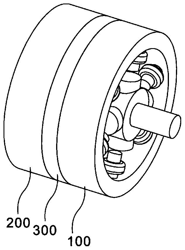
[0038] refer to figure 1 , provides a schematic diagram of the overall structure of a radial flux doubly salient permanent magnet motor integrated with a radial magnetic bearing, as shown in figure 1 , a radial flux doubly salient pole permanent magnet motor integrated with a radial magnetic bearing includes a rotating assembly 100, including a rotating member 101 and a stator body 102 arranged on the periphery of the rotating member 101; a suspension assembly 200, arranged on the rotating member 101 and the permanent magnet 300 is located between the suspension assembly 200 and the stator body 102 .
[0039]Specifically, the main structure of the present invention includes a rotating assembly 100, a suspension assembly 200, and a permanent magnet 300. Through the mutual cooperation between the rotating assembly 100 and the suspension assembly 200, the radial suspension force can be used to keep the rotating shaft in a non-contact state, eliminating the The friction loss caus...
Embodiment 2
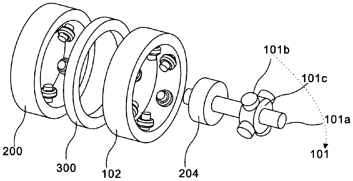
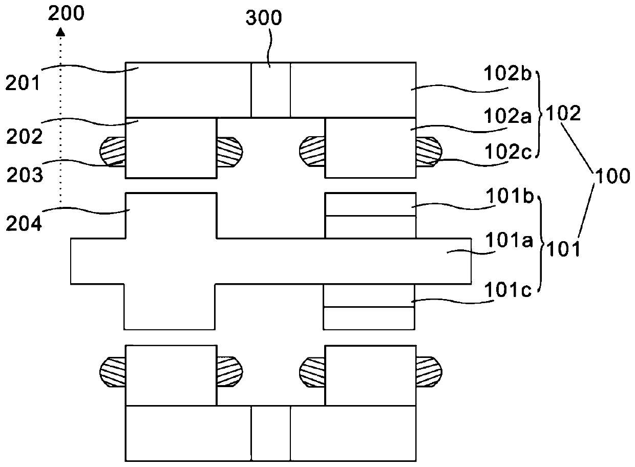
[0042] refer to figure 2 , this embodiment is different from the first embodiment in that: the levitation assembly 200 includes a magnetic bearing stator yoke 201, a magnetic bearing stator salient pole 202, a magnetic bearing control winding 203 and a magnetic bearing rotor 204, a magnetic bearing stator yoke 201, The magnetic bearing stator salient pole 202, the magnetic bearing control winding 203 and the magnetic bearing rotor 204 can respectively provide a bias magnetic field and a control magnetic field, and produce a controllable radial levitation force when the control magnetic field interacts with the excitation magnetic field. Due to the friction loss caused by mechanical contact during rotation, stable suspension in two degrees of freedom in the radial direction is realized. Specifically, the magnetic bearing stator yoke 201 of the suspension assembly 200 is disposed on one side of the permanent magnet 300 , wherein the magnetic bearing stator salient pole 202 of t...
Embodiment 3
[0047] refer to figure 2 , this embodiment is different from the above embodiments in that: the rotating member 101 also includes a motor rotor salient pole 101b and a motor rotor yoke 101c, and the set rotating shaft 101a, the motor rotor salient pole 101b and the motor rotor yoke 101c constitute the rotor of the motor , so that it can provide power for each machine. Specifically, the rotating member 101 also includes a motor rotor salient pole 101b and a motor rotor yoke 101c, the motor rotor salient pole 101b is arranged on the motor rotor yoke 101c, and the motor rotor yoke 101c is arranged outside the rotating shaft 101a; wherein, the magnetic bearing The rotor 204 is arranged on the rotating shaft 101a. It should be noted that the motor rotor yoke 101c is cylindrical, and the cylindrical motor rotor yoke 101c is sleeved on the rotating shaft 101a and rotates synchronously with the rotating shaft 101a. The surface protrudes outward along the direction perpendicular to t...
PUM
 Abstract
Description
Claims
Application Information
 - R&D
- Intellectual Property
- Life Sciences
- Materials
- Tech Scout
- Unparalleled Data Quality
- Higher Quality Content
- 60% Fewer Hallucinations
Browse by: Latest US Patents, China's latest patents, Technical Efficacy Thesaurus, Application Domain, Technology Topic, Popular Technical Reports.
© 2025 PatSnap. All rights reserved.Legal|Privacy policy|Modern Slavery Act Transparency Statement|Sitemap|About US| Contact US: help@patsnap.com