Horizontal linear motor structure and implementation method thereof

A horizontal linear motor technology, which is applied in the field of horizontal linear motor structure and its realization, can solve the problems of cost difference and fewer horizontal motors, and achieve the effects of consistent motion space, reduced stop time, and increased magnetic field utilization

Inactive Publication Date: 2020-03-27
ZHEJIANG DONGYANG CHENGJI ELECTRO MECHANICS CO LTD
View PDF11 Cites 11 Cited by
  • Summary
  • Abstract
  • Description
  • Claims
  • Application Information

AI Technical Summary

Problems solved by technology

Due to cost differences, there are more Z-axis linear motors and fewer horizontal motors currently on the market

Method used


Image

  • Horizontal linear motor structure and implementation method thereof
  • Horizontal linear motor structure and implementation method thereof
  • Horizontal linear motor structure and implementation method thereof

Examples


Embodiment 1

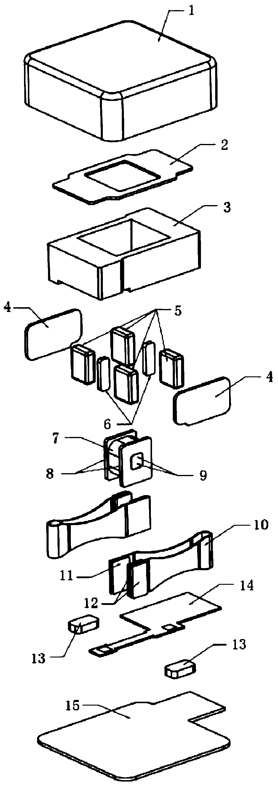
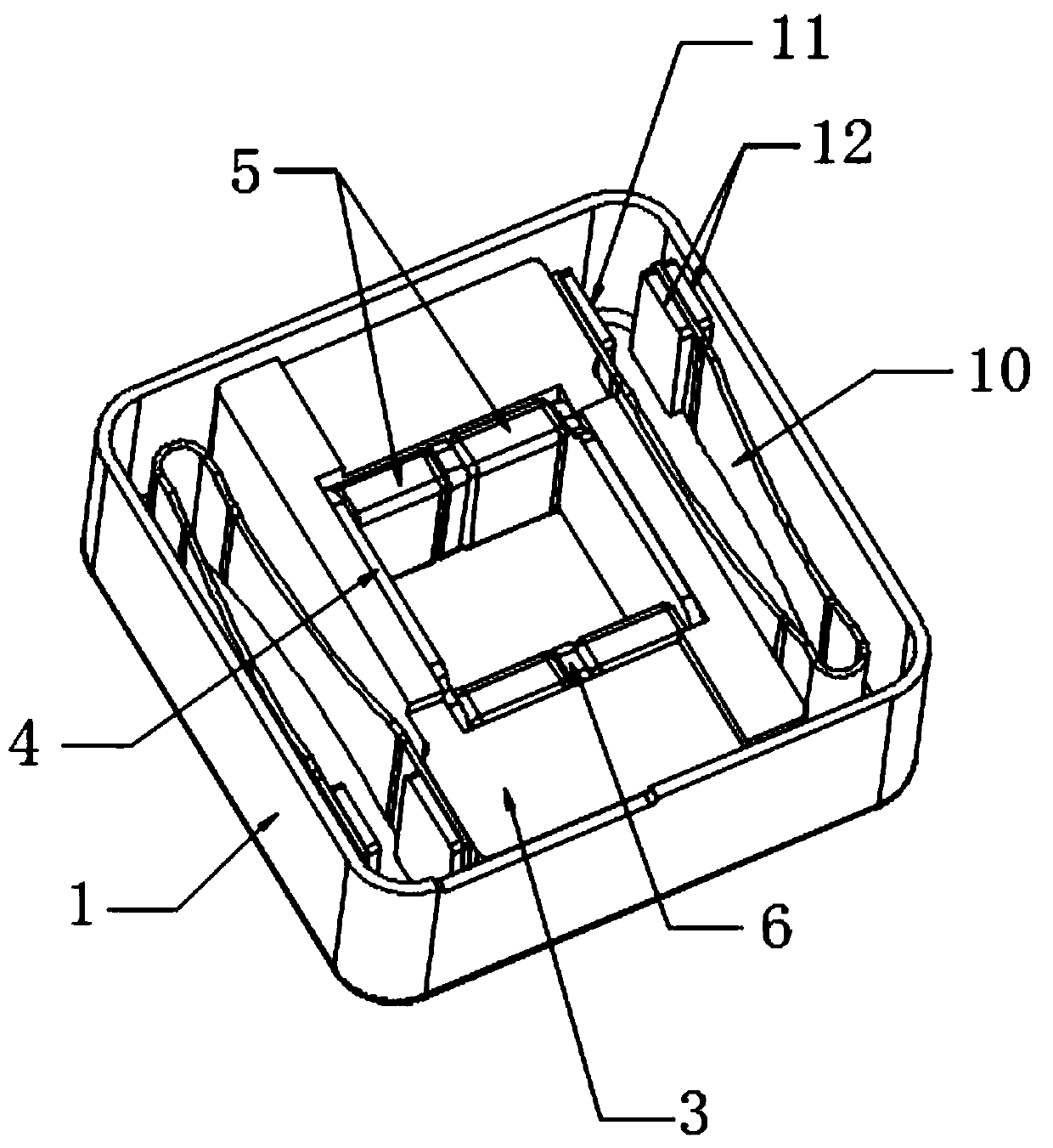
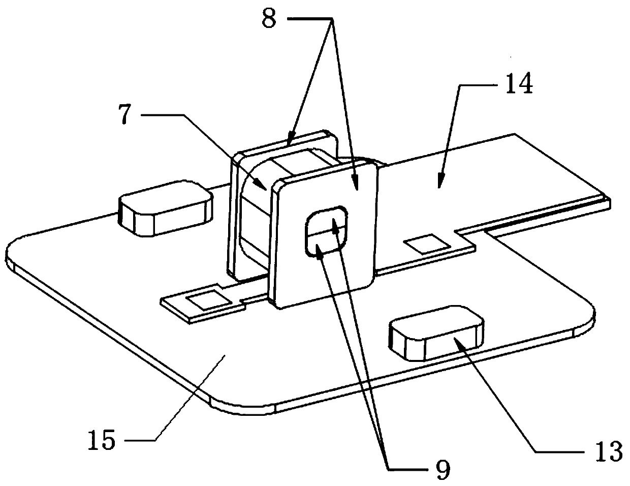
[0039] see Figure 1-6 , the present invention provides the following technical solutions: a horizontal linear motor structure, including a casing 1, a bottom plate 15 is connected to the bottom of the casing 1, a stator assembly is connected to the top of the bottom plate 15, a vibrator assembly is provided inside the casing 1, and the vibrator The assembly includes a mass block 3, a pole piece 4 and a magnetic steel assembly, wherein the opposite sides of the mass block 3 are respectively connected to a magnetic steel assembly, and the two sides of the magnetic steel assembly are connected to a pole piece 4, and the mass block 3 passes through a spring piece 10 Connected with the casing 1, the stator assembly includes a coil 7, an iron core 9 and an FPC circuit board 14, wherein the FPC circuit board 14 is connected above the bottom plate 15, and the coil 7 is arranged above the FPC circuit board 14, and the inside of the coil 7 is provided with There is an iron core 9, and ...

Embodiment 2

[0049] The difference between this embodiment and Embodiment 1 is that further, second stoppers 12 are respectively connected to both sides of the connecting arm connecting the spring leaf 10 and the casing 1, and the connecting arm connecting the spring leaf 10 and the mass block 3 is far away from the mass One side of the block 3 is connected with a first block 11 .

[0050] By adopting the above-mentioned technical scheme, the first stopper 11 and the second stopper 12 opposite to the first stopper 11 are used to fix the leaf spring 10, and weld the spring leaf 10 and the mass block 3, the spring leaf 10 and the casing 1 Provide welding flatness, strengthen the firmness of welding, and ensure the consistency of product frequency; the second stopper 12 between the casing 1 and the spring sheet 10 is used to increase the distance between the casing 1 and the spring sheet 10, ensuring The movement spaces on both sides of the spring leaf 10 are consistent.

[0051] Further, th...


PUM


Abstract

The invention discloses a horizontal linear motor structure which comprises a machine shell, a bottom plate is connected to the lower portion of the machine shell. A stator assembly is connected abovethe bottom plate; a vibrator assembly is arranged in the machine shell. The oscillator assembly comprises a mass block, a pole piece and a magnetic steel assembly. Two opposite sides in the mass block are respectively connected with a magnetic steel assembly, two sides of the magnetic steel assembly are connected with pole pieces, the mass block is connected with the machine shell through springpieces, the stator assembly comprises a coil, an iron core and an FPC circuit board, the FPC circuit board is connected above the base plate, and the coil is arranged above the FPC circuit board. Theinvention further discloses an implementation method of the horizontal linear motor structure. The magnetic steel, the yoke and the pole piece in the oscillator assembly, and the iron core and the support frame in the stator assembly form a magnetic field loop, so that the magnetic field is reserved in an effective area as much as possible, the utilization rate of the magnetic field is increased,the driving force is improved, and the magnetic field leakage is reduced.

Description

technical field [0001] The invention belongs to the technical field of linear motors, and in particular relates to a horizontal linear motor structure and a realization method thereof. Background technique [0002] Motors are the source of touch for smartphones, smart wearables and other products. With the increasing experience needs of users, the structure has also undergone earth-shaking changes. From cylindrical motors, to flat motors, to linear motors, the tactile sensations provided are becoming more and more diverse and refined. At present, in high-end equipment, in order to pursue the experience, linear motors are basically used across the board. Linear motors are divided into circular linear motors and square linear motors in shape, and Z-axis linear motors (vibration direction is the thickness direction) and horizontal linear motors (vibration direction is non-thickness direction) in the vibration direction. Due to cost differences, there are currently more Z-axis...

Claims


Application Information

Patent Timeline
Patent Type & Authority Applications(China)
IPC IPC(8): H02K33/02
CPCH02K33/02
Inventor 黄浩静王欣欣
Owner ZHEJIANG DONGYANG CHENGJI ELECTRO MECHANICS CO LTD
Why Eureka
Try Eureka