Garbage treatment device

A technology of a garbage disposal device and a flat plate, applied in the direction of presses, manufacturing tools, etc., can solve the problems of unavoidable landfill leachate, pollution, and inability to fully extrude landfill leachate, and achieve the effect of avoiding pollution of groundwater

Inactive Publication Date: 2020-03-31
YUNCHENG UNIVERISTY
View PDF1 Cites 5 Cited by
  • Summary
  • Abstract
  • Description
  • Claims
  • Application Information

AI Technical Summary

Problems solved by technology

However, this patent cannot fully squeeze out the landfill leachate in the garbage, and cannot prevent the landfill leachate from polluting groundwater.

Method used


Image

  • Garbage treatment device
  • Garbage treatment device
  • Garbage treatment device

Examples


specific Embodiment approach 1

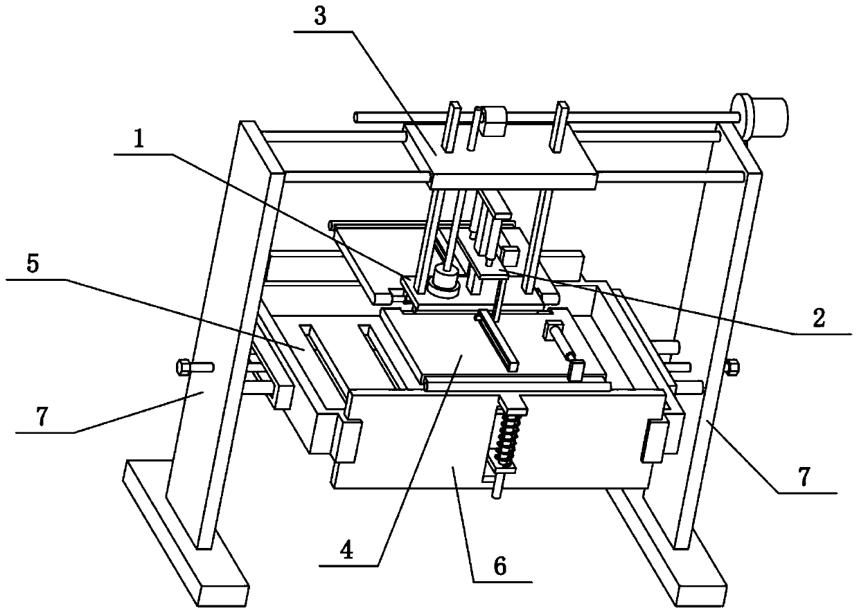
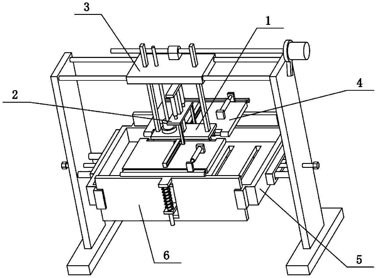
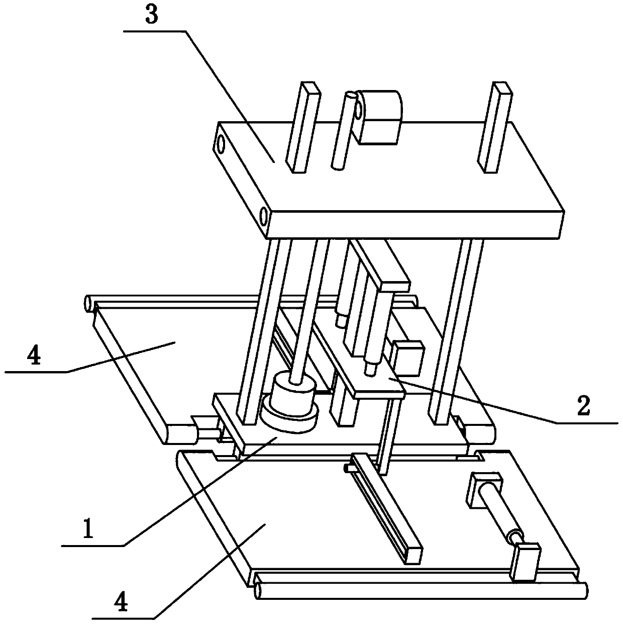
[0028] Combine below Figure 1-9 Describe this embodiment, the present invention relates to the field of garbage disposal, more specifically a garbage disposal device, including a flat plate 1, a convex strip 101, a top plate 104, an electric telescopic rod I105, a middle rod 106, a lifting plate 2, and a connecting strip 201 , sliding cylinder 202, pressing plate 4, major axis 401, sliding hole rod 402 and sliding hole 403, the present invention can fully squeeze out the landfill leachate in the rubbish, avoiding landfill leachate from polluting groundwater.

[0029] The front and rear ends of the lower side of the flat panel 1 are fixedly connected with convex strips 101, the upper center of the flat panel 1 is fixedly connected with a middle rod 106, and the middle rod 106 is slidably connected with a lifting plate 2, and the front and rear sides of the lower side of the lifting plate 2 Both ends are fixedly connected with connecting strips 201, the lower ends of the two co...

specific Embodiment approach 2

[0031] Combine below Figure 1-9 To illustrate this embodiment, the garbage disposal device also includes an electric telescopic rod II404, a convex seat 405 and a telescopic plate 406, the two pressure plates 4 are hollow structures, and the outer sides of the two pressure plates 4 are slidingly connected with the telescopic plate 406, two The upper side of the telescopic plate 406 is fixedly connected with the convex seat 405, the upper side of the two pressing plates 4 is fixedly connected with the electric telescopic rod II404, and the outer ends of the two electric telescopic rods II404 are fixedly connected with the two convex seats 405 respectively. When performing the operation of "making the angle between the two pressure plates 4 smaller", the two electric telescopic rods II404 are extended simultaneously, so that the two telescopic plates 406 are stretched out, and the area of ​​the two pressure plates 4 is enlarged, which is convenient for garbage disposal. The lef...

specific Embodiment approach 3

[0033] Combine below Figure 1-9 Referring to this embodiment, the garbage disposal device further includes a cylindrical edge 407, and the outer ends of the two telescopic plates 406 are both provided with a cylindrical edge 407. The cylindrical edge 407 reduces the frictional force on the lower part of the pressing plate 4 to prevent the two pressing plates 4 from being stuck when clamping the garbage.


PUM


Abstract

The invention relates to the field of garbage treatment, in particular to a garbage treatment device, which comprises a flat plate, convex strips, a top plate, first electric telescopic rods, a middlerod, a lifting plate, connecting strips, sliding cylinders, pressing plates, long shafts, a sliding hole rod and a sliding hole. Garbage leachate in garbage can be fully extruded out, and undergroundwater is prevented from being polluted by the garbage leachate. The convex strips are fixedly connected to the front and rear ends of the lower side of the flat plate; the middle rod is fixedly connected to the center of the upper side of the flat plate; the lifting plate is slidably connected to the middle rod; the connecting strips are fixedly connected to the front and rear ends of the lower side of the lifting plate; the sliding cylinders are fixedly connected to the lower ends of the two connecting strips; the upper end of the middle rod is fixedly connected with the top plate; the firstelectric telescopic rods are fixedly connected to the front end and the rear end of the lower side of the top plate correspondingly; the lower ends of the two first electric telescopic rods are fixedly connected to the upper side of the lifting plate; the two pressing plates are symmetrically arranged front and back; the long shafts are arranged at the inner ends of the two pressing plates correspondingly; and the two pressing plates are hinged to the two convex strips through the long shafts correspondingly.

Description

technical field [0001] The invention relates to the field of garbage disposal, in particular to a garbage disposal device. Background technique [0002] The application number is CN201620152654.0, which discloses a waste treatment device. The utility model relates to a waste treatment device, in particular to a medical iron waste treatment device. The technical problem to be solved by the utility model is to provide a medical iron waste disposal device capable of compressing iron waste and convenient for packing. In order to solve the above-mentioned technical problems, the utility model provides such a medical iron waste disposal device, which includes a left bracket, a right bracket, an I-beam, a slide rail, a slider I, a slider II, an electric wheel, a driven wheel, Steel wire rope Ⅰ, hook, basket, hoist, wire rope Ⅱ, mesh bottom plate, cylinder, furnace, baffle, support rod, shell, compression chamber, hopper, high manganese steel pressure head and hydraulic cylinder; l...

Claims


Application Information

Patent Timeline
Patent Type & Authority Applications(China)
IPC IPC(8): B30B9/06B30B15/06
CPCB30B9/06B30B15/062
Inventor 张晓斌
Owner YUNCHENG UNIVERISTY
Why Eureka
Try Eureka