An x-axis reciprocating vibrating motor for a mixing tank
A technology of vibrating motor and mixing barrel, applied in the field of vibrating motor and X-axis reciprocating vibration motor, can solve the problem of easy accumulation of dust and so on
- Summary
- Abstract
- Description
- Claims
- Application Information
AI Technical Summary
Problems solved by technology
Method used
Image
Examples
Embodiment 1
[0026] Such as Figure 1-2 As shown, the present invention provides an X-axis reciprocating vibration motor for a mixing tank, including an electromagnet mechanism 1, the electromagnet mechanism 1 is connected with a permanent magnet 3 through a sliding shaft 2, and the sliding shaft 2 is fixedly installed on On the side of the permanent magnet 3, the bottom of the electromagnet mechanism 1 is provided with a base 4, the electromagnet mechanism 1 includes a casing 11, and a side chute 12 is dug through on the side panel of the casing 11, and the sliding shaft rod 2 is slidably arranged on In the side chute 12 , the inner two ends of the casing 11 are respectively connected with the two ends of the electromagnet body 14 through the mounting base 13 , and the bottom surface of the casing 11 is fixedly mounted with a welding surface 15 .
[0027] In this embodiment, through the magnetic interaction between the designed permanent magnet 3 and the electromagnet body 14, the present...
Embodiment 2
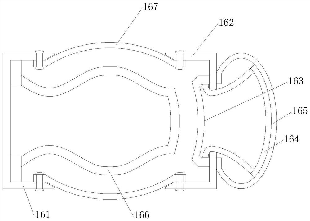
[0029] Such as image 3 As shown, on the basis of Embodiment 1, the present invention provides a technical solution: the buffer 16 includes a welding seat 161, one side of the welding seat 161 is provided with a moving cover 162, and the middle of the moving cover 162 is fixedly welded with an elastic frame 163, one end of the supporting leg of the elastic frame 163 passes through the movable cover 162 and is fixedly connected to the arc-shaped supporting surface 164, the arc-shaped supporting surface 164 is arranged in the rubber ball 165, and the port of the rubber ball 165 and the moving cover 162 are away from the welding seat 161 One side is sealed and connected, and a rebound frame 166 is provided in the middle of one side of the welding seat 161 close to the moving cover 162 , and a drum ball 167 is provided between the welding seat 161 and the moving cover 162 .
[0030] In this embodiment, the rubber ball 165 is provided so that when the permanent magnet 3 impacts the...
Embodiment 3
[0032] Such as image 3 , 5 As shown, on the basis of Embodiment 1, the present invention provides a technical solution: the rebound frame 166 includes a contact surface b1, the contact surface b1 is a square arc panel, and the inner four corners of the contact surface b1 are provided with mute cotton b2, The mute cotton b2 is an S-shaped square rod, and the mute cotton b2 on the opposite side of the contact surface b1 is symmetrical about the contact surface b1. The outer surface of the contact surface b1 is fixedly bonded with a curved leg b3, and the curved leg b3 is compatible with the elastic The frame 163 is correspondingly arranged.
[0033] In this embodiment, the contact surface b1 is designed to contact the elastic frame 163, so that the displacement pressure on the elastic frame 163 is transmitted to the rebound frame 166. At the same time, the contact surface b1 distributes the force and transmits it to the four mutes. Cotton b2 makes the stress conditions of the...
PUM
 Abstract
Description
Claims
Application Information
 - R&D
- Intellectual Property
- Life Sciences
- Materials
- Tech Scout
- Unparalleled Data Quality
- Higher Quality Content
- 60% Fewer Hallucinations
Browse by: Latest US Patents, China's latest patents, Technical Efficacy Thesaurus, Application Domain, Technology Topic, Popular Technical Reports.
© 2025 PatSnap. All rights reserved.Legal|Privacy policy|Modern Slavery Act Transparency Statement|Sitemap|About US| Contact US: help@patsnap.com


