Marking device for road construction

A scribing device and road construction technology, applied in roads, roads, road repairs, etc., can solve the problems of inconvenient adjustment of scribing width, uneven paint mixing, etc., to solve the problem of uneven paint mixing, uniform paint mixing, and prevent precipitation Effect

Inactive Publication Date: 2020-03-31
王敏帆
View PDF0 Cites 8 Cited by
  • Summary
  • Abstract
  • Description
  • Claims
  • Application Information

AI Technical Summary

Problems solved by technology

[0003] During the scribing process of the existing scribing device, the paint is not evenly mixed, and the scribing width is inconvenient to adjust

Method used


Image

  • Marking device for road construction
  • Marking device for road construction
  • Marking device for road construction

Examples


Embodiment 1

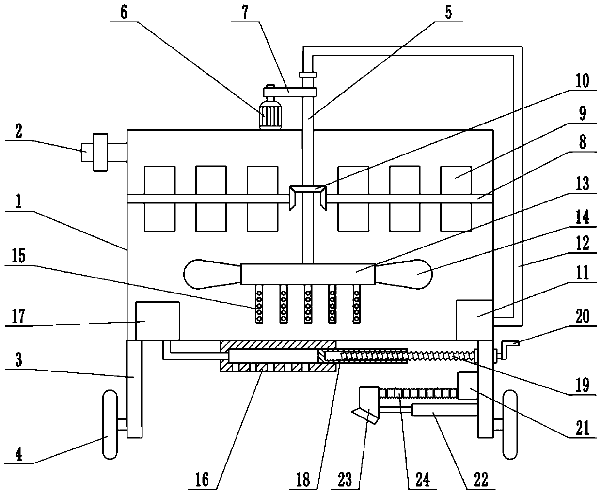
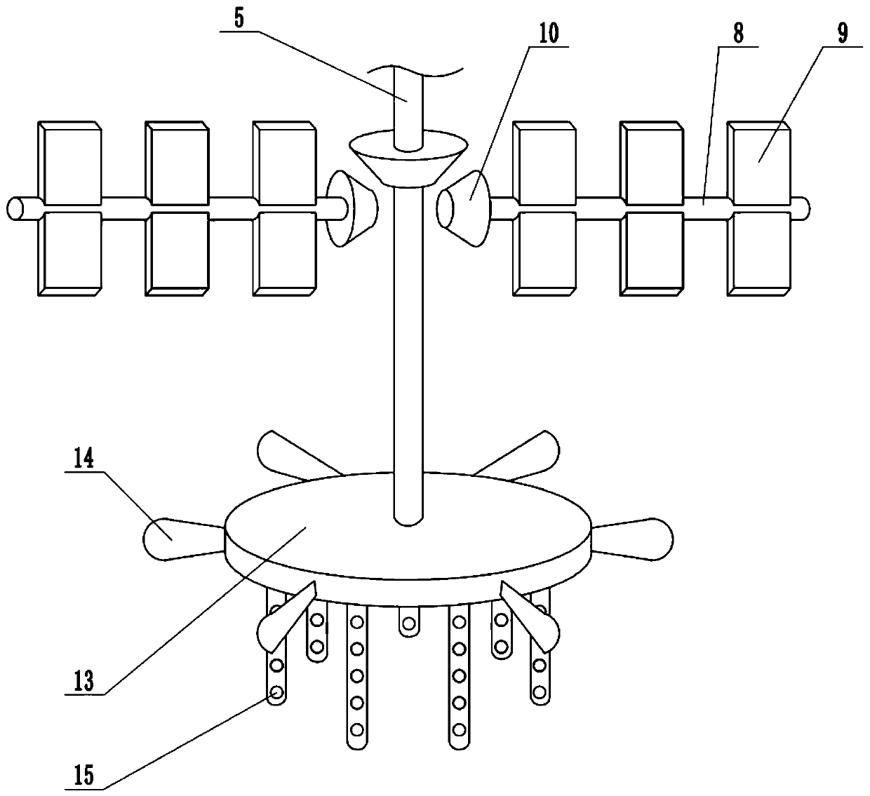
[0024] see Figure 1-3 , in an embodiment of the present invention, a marking device for road construction, including a box body 1, a support plate 3, a roller 4, a spray plate 16 and a booster pump 17, and a feed pipe is installed on the side wall of the box body 1 2. The paint used for scribing is injected into the box body 1 through the feed pipe 2. The bottom of the box body 1 is equipped with a support plate 3. There are two support plates 3, which are arranged symmetrically on the left and right. A hollow shaft 5 is installed inside the body 1, and the upper end of the hollow shaft 5 extends through the top of the box 1 to the top of the box 1. The hollow shaft 5 is connected to the top of the box 1 in rotation, and the upper surface of the box 1 is fixedly connected. There is a motor 6, and the whole body of the motor 6 is connected with the hollow rotating shaft 5 through the transmission belt 7. When the motor 6 is running, the hollow rotating shaft 5 is driven to rot...

Embodiment 2

[0026] On the basis of Embodiment 1, a dryer 21 is fixedly connected to the side wall of the support plate 3, and a telescopic mechanism 22 is arranged below the dryer 21. The telescopic mechanism 22 is an electro-hydraulic telescopic cylinder. The support plate 3 is fixedly connected, and the extended end of the telescopic mechanism 22 is fixedly connected with an air outlet 23. The air outlet of the dryer 21 communicates with the air outlet 23 through a telescopic hose 24, and the hot air generated by the dryer 21 passes through the telescopic hose. 24 is transported to the air outlet 23, and then sprayed out through the air outlet 23 to dry the paint on the ground and improve the marking efficiency.

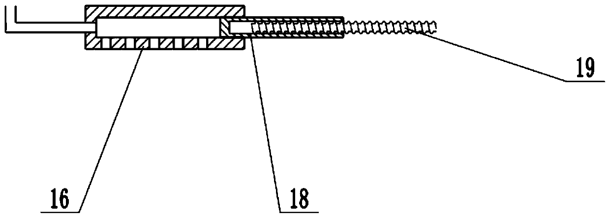
[0027] Combined with Embodiment 1 and Embodiment 2, the working principle of the present invention is: inject the paint bucket feed pipe 2 into the box body 1, and when it is necessary to carry out the marking operation, turn the handle 20 to drive the screw rod 19 to rotate, t...


PUM


Abstract

The invention relates to the field of road construction equipment. More particularly, the present invention relates to a marking device for road construction. The device comprises a box body, a support plate, rollers, a spraying plate and a booster pump, the suppor plate is mounted at the bottom of the box body; a hollow rotating shaft is mounted in the box body; a stirring shaft is mounted in thebox body; a rotary joint is mounted at the top end of the hollow rotating shaft; a circulating pump is mounted at the bottom of the box body; stirring discs are mounted at the lower end of the hollowrotating shaft; the lower surface of the box body is fixedly connected with a spraying plate; the booster pump is mounted at the bottom of the box body; the crank is rotated to drive the movable plate to move left and right in the spraying plate; depending on actual scribing requirements, in the marking process, the motor is started, the stirring plate is used for stirring upper-layer paint to enable the paint to be evenly mixed, the stirring blades and the stirring rod are used for stirring bottom-layer paint to enable the paint to be mixed more evenly, precipitation of the paint is prevented, and the circulating pump is used for achieving circulating stirring of the paint to enable the paint to be mixed more evenly.

Description

technical field [0001] The invention relates to the field of road construction equipment, more specifically, a marking device for road construction. Background technique [0002] Road marking is mainly drawn on the road surface, which is exposed to the sun, rain, wind, snow and ice, and is subjected to the impact and wear of vehicles, so there are strict requirements on its performance. It is a safety sign and a "language" in road traffic. [0003] During the scribing process of the existing scribing device, the paint mixing is not uniform enough, and the scribing width is inconvenient to adjust. Contents of the invention [0004] The purpose of the present invention is to provide a marking device for road construction, so as to solve the problems raised in the above-mentioned background technology. [0005] To achieve the above object, the present invention provides the following technical solutions: [0006] A marking device for road construction, including a box body...

Claims


Application Information

Patent Timeline
Patent Type & Authority Applications(China)
IPC IPC(8): E01C23/22B01F7/00B01F7/04B01F7/16B01F7/26B01F5/10B01F13/00B01F27/93
CPCE01C23/227B01F25/52B01F27/192B01F27/2121B01F27/2124B01F27/232B01F27/2323B01F27/706B01F27/811B01F27/93B01F33/502B01F2101/30
Inventor 王敏帆
Owner 王敏帆
Why Eureka
Try Eureka