Radial diffuser and centrifugal compressor

A radial diffuser and rotating body technology, applied in machines/engines, mechanical equipment, liquid fuel engines, etc., can solve problems such as atmospheric flow loss, high compressor efficiency, and reduced compressor efficiency.

Pending Publication Date: 2020-03-31
新奥能源动力科技(上海)有限公司
View PDF0 Cites 4 Cited by
  • Summary
  • Abstract
  • Description
  • Claims
  • Application Information

AI Technical Summary

Problems solved by technology

like figure 2 The schematic diagram of the airflow direction at the inlet of the vane channel of the radial diffuser 4 is shown. Arrow a, arrow b, and arrow c respectively indicate different airflow directions. Under design conditions, the airflow direction at the inlet of the radial diffuser is for figure 2 The arrow b in the figure is the most ideal. At this time, the common angle of attack of the airflow is 0°, the airflow loss is the smallest, and the compressor efficiency is the highest; The direction of the air changes, becoming figure 2 In the airflow direction indicated by the arrow a or arrow c, the intake angle of attack is not 0° at this time, so it will bring a large airflow loss, resulting in a decrease in the efficiency of the compressor

Method used


Image

  • Radial diffuser and centrifugal compressor
  • Radial diffuser and centrifugal compressor
  • Radial diffuser and centrifugal compressor

Examples


Embodiment Construction

[0036] In order to make the purpose, technical solutions and advantages of the present invention clearer, the present invention will be further described in detail below in conjunction with the accompanying drawings. Obviously, the described embodiments are only some of the embodiments of the present invention, rather than all of them. Based on the embodiments of the present invention, all other embodiments obtained by persons of ordinary skill in the art without making creative efforts belong to the protection scope of the present invention.

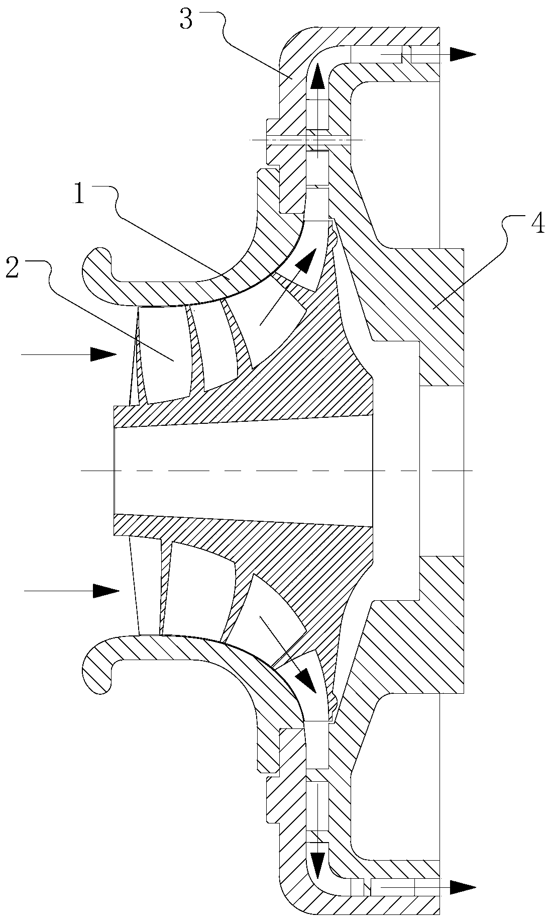
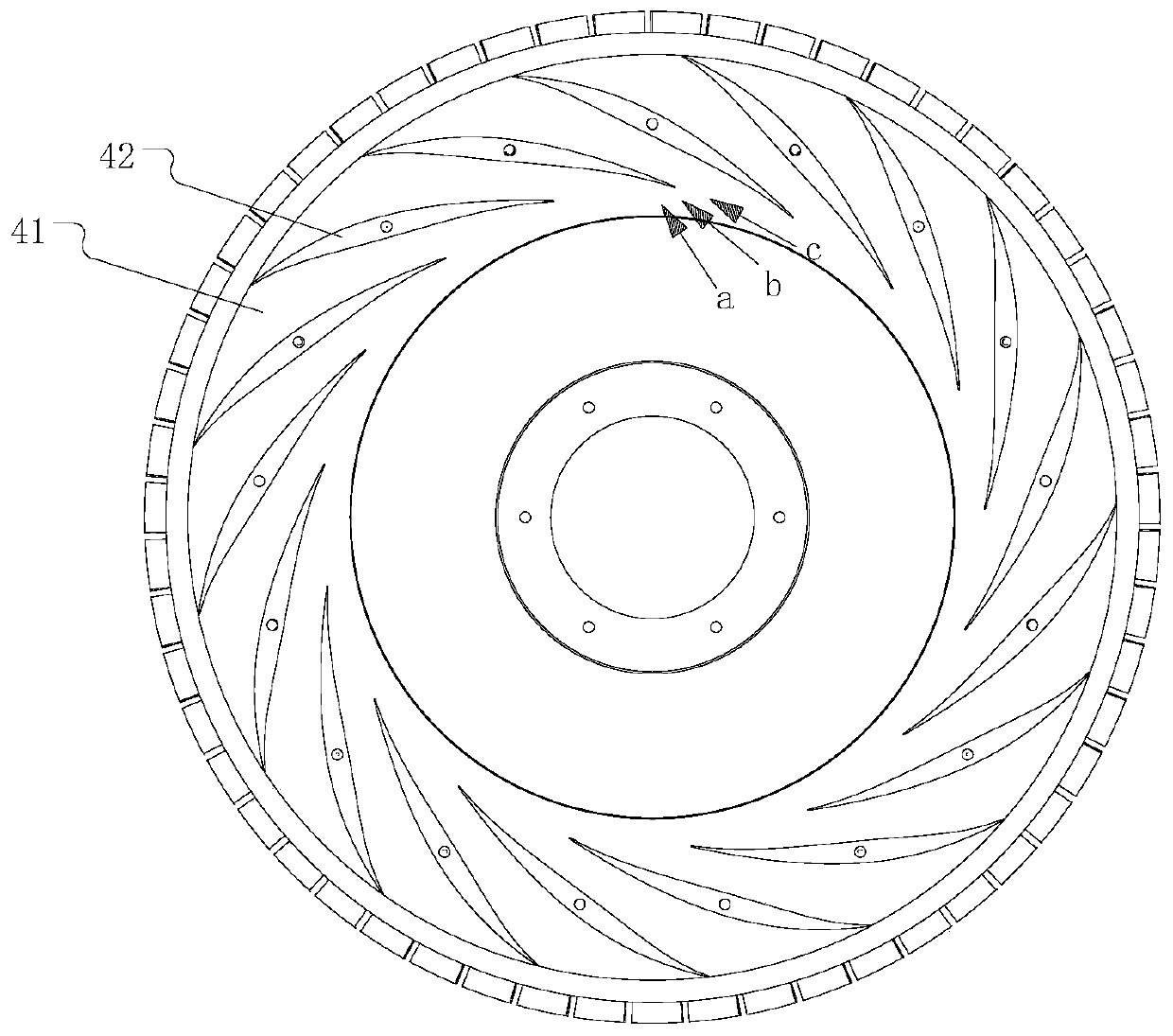
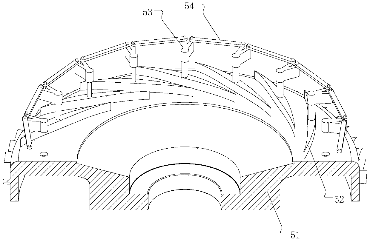
[0037] The embodiment of the present invention provides a radial diffuser, which separates the blades from the chassis as a separate structure, and enables the blades to rotate relative to the chassis to adapt to incoming flows in different directions and reduce the angle of attack of the intake air. Specifically, the radial diffuser includes a chassis and a plurality of blades arranged on the chassis, and these blades are arranged at in...


PUM


Abstract

The invention relates to the technical field of centrifugal compressors, and discloses a radial diffuser and a centrifugal compressor. The radial diffuser comprises a chassis and a plurality of blades, wherein the blades are arranged at intervals along the circumference relative to the center of the chassis. The radial diffuser further comprises a plurality of rotating bodies, wherein each rotating body is provided with a rotating shaft, and the rotating shafts penetrate through the corresponding blades and then are rotationally connected with the chassis; every two adjacent rotating bodies are provided with an adjusting connecting rod therebetween, for each adjusting connecting rod, the rotating bodies located at two ends of the adjusting connecting rod are a first rotating body and a second rotating body respectively, and the adjusting connecting rod is rotationally connected with the first rotating body and the second rotating body respectively; the connecting line between the projection of the rotating shaft on the first rotating body and the projection of the rotating shaft on the second rotating body on the chassis is parallel to and equal to the projection of the adjusting connecting rod on the chassis in length; when one of the adjusting connecting rods is pulled, the rotating body is driven by the adjusting connecting rod to rotate relative to the chassis, and the corresponding blade is enabled to rotate by a set angle.

Description

technical field [0001] The invention relates to the technical field of centrifugal compressors, in particular to a radial diffuser and a centrifugal compressor. Background technique [0002] figure 1 It is a single-stage centrifugal compressor with radial and axial diffusers commonly used at present, including compressor inlet casing 1, compressor impeller 2 (including impeller blades), diffuser mounting plate 3, radial diffuser Compressor 4 and axial diffuser. The working principle of the centrifugal compressor is: the rotating shaft drives the compressor impeller 2 to rotate at a high speed, and the compressor impeller 2 sucks air at normal temperature and pressure from the atmospheric environment, and does work on the air to make the air Both pressure and temperature rise. After the air is thrown out from the outlet of the compressor impeller 2, it enters the channel surrounded by the diffuser mounting plate 3 and the diffuser (radial diffuser 4 and axial diffuser) ( f...

Claims


Application Information

Patent Timeline
Patent Type & Authority Applications(China)
IPC IPC(8): F04D29/46F04D27/02
CPCF04D27/0246F04D29/444F04D29/462
Inventor 康环王威威李乃宇韩孟克刘亚东白生玮陈泽文
Owner 新奥能源动力科技(上海)有限公司
Why Eureka
Try Eureka