A remote control visual cable cutting device

A visual cable and cutting device technology, applied in cable installation devices, cable installation, equipment for dismantling/armored cables, etc., can solve the problems of low cable cutting efficiency and low safety risk, and ensure the connection strength and stability. performance, reduce safety risks, and increase cutting efficiency

Active Publication Date: 2020-11-24
STATE GRID ZHEJIANG JIASHAN POWER SUPPLY CO LTD +2
View PDF13 Cites 0 Cited by
  • Summary
  • Abstract
  • Description
  • Claims
  • Application Information

AI Technical Summary

Problems solved by technology

[0004] In order to overcome the problems of low cable cutting efficiency in the prior art, the construction process is very close to the cable to be cut, and there are safety risks such as arc burns or step voltage injury, the present invention provides a remote control visible cable cutting device. The cable can be controlled and cut remotely, the cutting operator is far away from the cable, does not require too much safety protection, has the advantages of high cutting efficiency and low safety risk

Method used


Image

  • A remote control visual cable cutting device
  • A remote control visual cable cutting device
  • A remote control visual cable cutting device

Examples


Embodiment 1

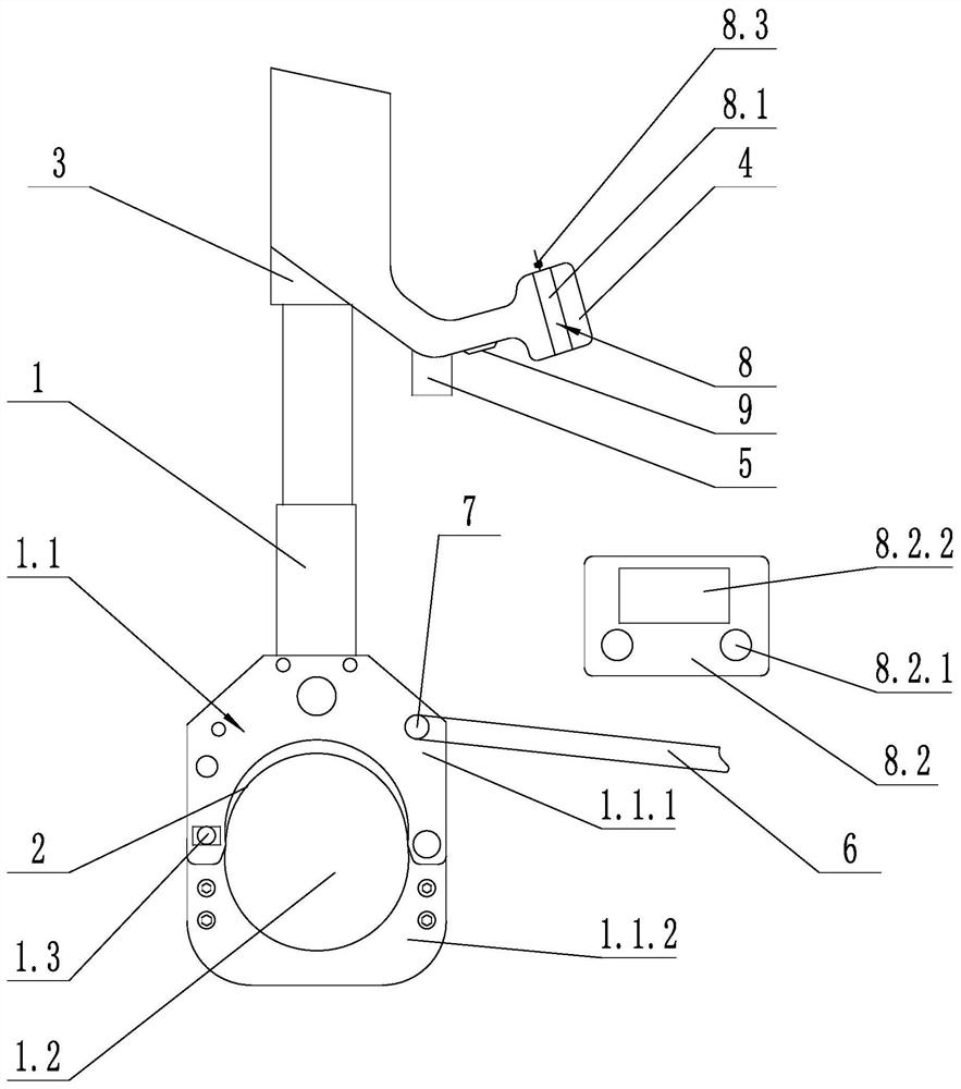
[0030] Such as figure 1 As shown, a remote control visual cable cutting device includes a support frame 1, a blade 2, a driving device 3, a battery 4, a camera 5, a remote control device 8, a ground wire 6, a current sensor 7 and a power switch 9; the driving device 3 It is an electro-hydraulic device, the telescopic rod of the electro-hydraulic device is connected with the blade 2; the support frame 1 includes a cable support 1.1, and the cable support 1.1 includes a fixed part 1.1.1 and a movable part 1.1.2, and a fixed part 1.1.1 and a movable part 1.1.2 Enclose the cable accommodation groove 1.2, the blade 2 is slidingly connected with the fixing part 1.1.1, and the knife edge of the blade 2 faces the cable accommodation groove 1.2; one end of the grounding wire 6 is electrically connected through the support frame 1 of the current sensor 7, the The other end is grounded; the power switch 9 is fixed on the support frame 1 and electrically connected to the battery 4, the re...

Embodiment 2

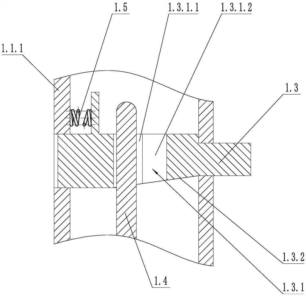
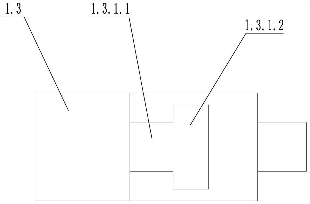
[0033] Such as figure 2 , image 3 and Figure 4 As shown, on the basis of Embodiment 1, one end of the movable part 1.1.2 is hinged with the fixed part 1.1.1, the other end of the movable part 1.1.2 is clamped with the fixed part 1.1.1, and the fixed part 1.1.1 There is a sliding locking part 1.3 and a telescopic spring 1.5, the sliding locking part 1.3 is slidably connected with the fixing part 1.1.1, one end of the telescopic spring 1.5 is connected with the sliding locking part 1.3, and the other end of the telescopic spring 1.5 is connected with the fixing part 1.1.1 ; The sliding locking member 1.3 is provided with a locking groove 1.3.1, and the locking groove 1.3.1 includes a locking groove 1.3.1.1 and a passing groove 1.3.1.2 which are connected to each other and arranged in sequence along the sliding direction of the sliding locking member 1.3, and the sliding lock The end of the tightening part 1.3 close to the movable part 1.1.2 is provided with a locking slope ...


PUM


Abstract

The invention discloses a remote control visual cable cutting device, which comprises a support frame, a blade, a driving device, a battery, a camera and a remote controller. The blade is slidably connected with the support frame. The blade is used for cutting a cable. The driving device is used for driving the blade to move, and is fixed to the support frame. The battery is used for supplying power to electric components such as the driving device; the camera is used for monitoring the cutting condition of the blade, is fixed with the support frame and is aligned with the blade; and the remote control device is used for remotely controlling the driving device and the camera. The remote control visual cable cutting device provided by the invention can remotely control and cut a cable, a cutting operator is far away from the cable, excessive safety protection is not needed, and the remote control visual cable cutting device has the advantages of high cutting efficiency, low safety riskand the like.

Description

technical field [0001] The invention relates to the technical field of power equipment maintenance tools, in particular to a remote-controlled visible cable cutting device. Background technique [0002] With the rapid development of economy and society, people have higher and higher requirements for the reliability of power supply, and the construction of distribution network is also developing towards insulation and cable. Among them, during the construction of cable lines, it is necessary to cut and reconnect the original cable lines and adjust the wiring mode to continuously improve the structure of the cable line grid. However, the current cable cutting generally adopts the method of manual cutting, which takes a long time to cut, low work efficiency and high risk. For example, to cut a cable, it needs to go through four steps: the first step is to check the cable routing according to the drawing; the second step is to take safety measures on the construction site; One...

Claims


Application Information

Patent Timeline
Patent Type & Authority Patents(China)
IPC IPC(8): H02G1/12
CPCH02G1/1256
Inventor 史建勋徐勇明曹吉领陈宇袁绍山张冲标郁云忠戴元安冯超施正栋潘桐岐唐洪伟范付元朱迪李俊
Owner STATE GRID ZHEJIANG JIASHAN POWER SUPPLY CO LTD
Why Eureka
Try Eureka