
Clamping mechanism used during machining of bolt sphere reference surface

A clamping mechanism and datum surface technology, used in metal processing mechanical parts, metal processing equipment, clamping and other directions, can solve the problems of poor parallelism, low precision, poor precision, etc., to improve stability and reliability, Good stability and reliability, and the effect of improving the clamping effect

Active Publication Date: 2020-04-03
LENGSHUIJIANG TIANBAO IND
View PDF8 Cites 3 Cited by
  • Summary
  • Abstract
  • Description
  • Claims
  • Application Information

AI Technical Summary

Problems solved by technology

[0005] The invention provides a clamping mechanism for processing the datum plane of a bolt ball, which has high clamping stability and reliability for the sphere, so that the accuracy and parallelism of the two sets of datum planes are better. For the second group The reference plane does not need to be re-clamped and positioned, and the advantages of high cutting efficiency solve the problem that the three-jaw chuck is used to fix the bolt ball reference plane at present, but because the bolt ball is a The ball structure makes it point-contact with the chuck, and it is easy to roll and tilt during the cutting process, which leads to poor parallelism and precision between the two sets of datum planes. Due to the curved surface structure of the sphere, it is difficult to ensure that the first set of reference planes are always in a horizontal state during the clamping process when cutting the second set of reference planes, and it is easy to appear in the clamping process. The phenomenon of rolling and tilting leads to the problem of low machining efficiency and poor precision of the bolt ball datum surface

Method used


Image

  • Clamping mechanism used during machining of bolt sphere reference surface
  • Clamping mechanism used during machining of bolt sphere reference surface
  • Clamping mechanism used during machining of bolt sphere reference surface

Examples


Embodiment Construction

[0022] The following will clearly and completely describe the technical solutions in the embodiments of the present invention with reference to the accompanying drawings in the embodiments of the present invention. Obviously, the described embodiments are only some, not all, embodiments of the present invention. Based on the embodiments of the present invention, all other embodiments obtained by persons of ordinary skill in the art without making creative efforts belong to the protection scope of the present invention.

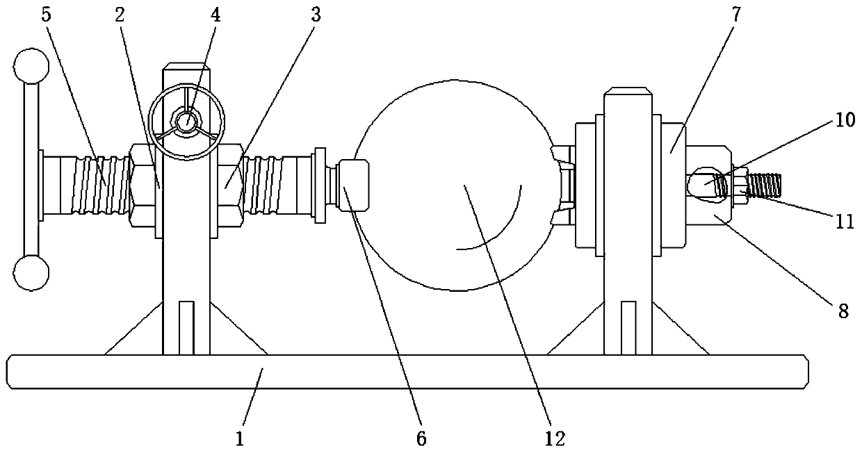
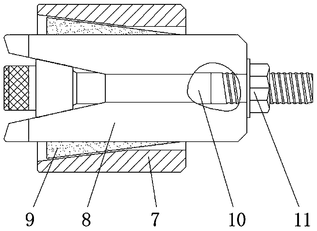
[0023] see Figure 2-4 , a clamping mechanism for processing bolt ball datum planes, comprising a mounting base 1, a fixed sleeve 2 is fixedly installed inside the left side of the mounting base 1, and a locking nut 3 is movable inside the fixed sleeve 2, and The fixed sleeve 2 and the lock nut 3 are connected through the transmission of the adjustment mechanism 4. The inner thread of the lock nut 3 is connected with a lock screw 5, and the right end of the lo...


PUM


Abstract

The invention relates to the technical field of sphere machining equipment, and discloses a clamping mechanism used during machining of a bolt sphere reference surface. The clamping mechanism comprises a mounting base, wherein a fixing sleeve is fixedly arranged inside the left side of the mounting base, the inside of the fixing sleeve is movably connected with a locking nut in a sleeving mode, the fixing sleeve is in transmission connection with the locking nut through an adjusting mechanism, a locking screw rod is in threaded connection with the inside of the locking nut, a fixed pressing plate is arranged at the right end of the locking screw rod, and the inside of the right side of the mounting base is movably connected with an adjusting sleeve in a sleeving mode. According to the clamping mechanism used during machining of the bolt sphere reference surface, through the arrangement of a three-claw pressure rod, the pressure can be simultaneously applied to one side of a bolt spherefrom three directions, and with the cooperation of the extrusion by the fixed pressure plate, the bolt sphere can be stably and effectively fixed at a certain position, the problem of rolling or tilting due to cutting stress is avoided, and the stability and the reliability of the clamping mechanism are effectively improved.

Description

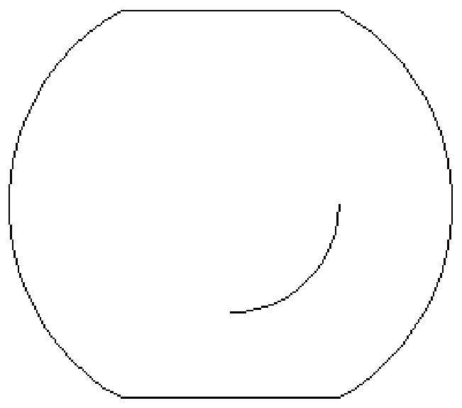
technical field [0001] The invention relates to the technical field of sphere processing equipment, in particular to a clamping mechanism for processing a bolt ball datum plane. Background technique [0002] Bolt ball is a grid structure with multiple holes containing internal threads on the sphere to connect multiple connecting rods at one point. Cutting processing, processing and forming of threaded holes, etc., where the datum plane is used as the processing standard of the threaded hole, which can directly affect the processing accuracy of the threaded hole. [0003] Moreover, the datum planes of the bolt balls are usually arranged in two groups and symmetrically (such as figure 1 shown), in order to avoid the influence of the fixed fixture on the cutting tool when cutting the threaded hole. At present, when cutting the datum plane of the bolt ball, the method of fixing the three-jaw chuck is adopted, but due to The bolt ball is a spherical structure, which makes it po...

Claims


Application Information

Patent Timeline
IPC IPC(8): B23Q3/06B23Q3/00
CPCB23Q3/06B23Q3/00B23Q3/062
Inventor 吴明贵
Owner LENGSHUIJIANG TIANBAO IND
Learn More