Assembly type lightweight carriage
A lightweight, prefabricated technology, used in vehicle components, transportation and packaging, and the superstructure of trucks, etc., can solve problems such as increased transportation costs, overall deformation of the carriage, and weld fractures, and achieves weight reduction, increase. High strength and damage reduction effect
- Summary
- Abstract
- Description
- Claims
- Application Information
AI Technical Summary
Problems solved by technology
Method used
Image
Examples
Embodiment 1
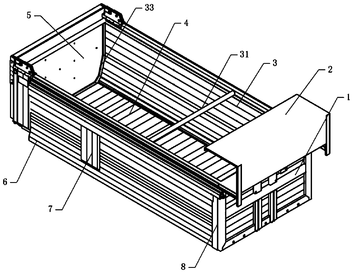
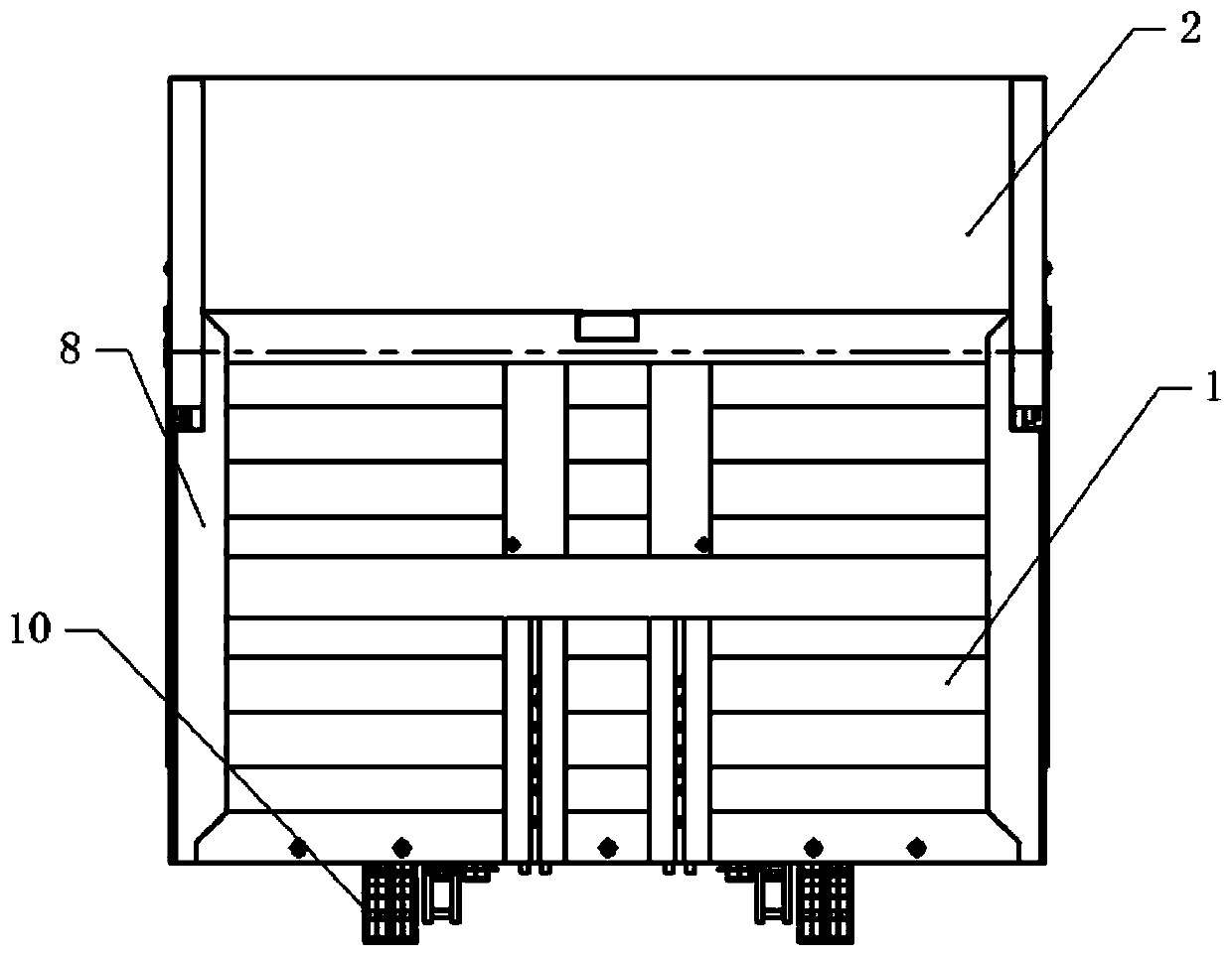
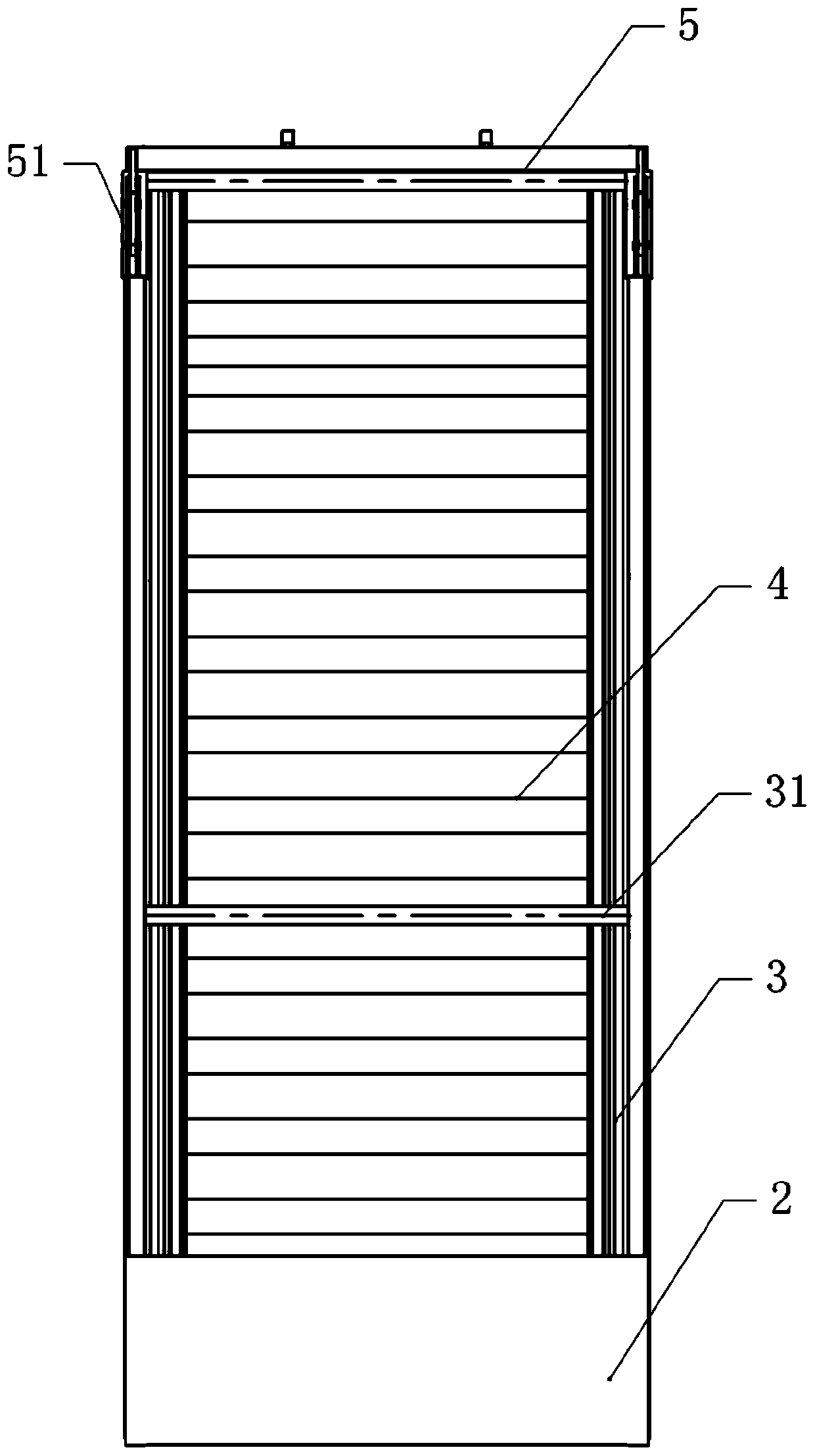
[0042] Basic as attached figure 1 And attached image 3 As shown, an assembled lightweight carriage includes a front panel 1 , side panels 3 and a bottom panel 4 . The front plate 1 is formed by friction welding of several hollow mouth plates, the side plate 3 is formed by friction welding of several hollow mouth plates, and the bottom plate 4 is formed by friction welding of several hollow mouth plates. The following advantages can be achieved through friction welding: no need to rely on skilled welders; minimal preparation work; no need for flux or shielding gas; good for the environment, no welding fumes or other gases.
[0043] The side plates 3 are two pieces, which are respectively located on both sides of the bottom plate 4. Between the side plates 3, reinforcing beams 31 whose two ends are respectively welded on the side plates 3 are arranged, and the connection strength of the two side plates 3 is enhanced through the reinforcing beams 31. In this embodiment, the cr...
Embodiment 2
[0053] The difference between embodiment two and embodiment one is that, as attached figure 1 And attached figure 2 As shown, the inner wall of the side plate 3 is provided with an expansion surface 33, the outer wall of the side plate 3 is welded with a support plate 6, and the two sides of the front plate 1 are welded with guide frocks. In this embodiment, the guide frock is a guide plate 8. combined with Image 6 As shown, the support plate 6 is composed of several mouth plates through friction welding, and the cross section of the support plate 6 is triangular.
[0054] The specific implementation process is as follows:
[0055] When the front plate 1 is connected with the side plate 3, it is guided by the guide plate 8, as attached Figure 8 As shown, the front locking groove 122 and the side locking groove 121 are aligned through the guide plate 8, so that the front plate 1 and the side plate 3 are aligned, so as to facilitate the installation of the locking beam 12 ...
PUM
 Abstract
Description
Claims
Application Information
 - R&D
- Intellectual Property
- Life Sciences
- Materials
- Tech Scout
- Unparalleled Data Quality
- Higher Quality Content
- 60% Fewer Hallucinations
Browse by: Latest US Patents, China's latest patents, Technical Efficacy Thesaurus, Application Domain, Technology Topic, Popular Technical Reports.
© 2025 PatSnap. All rights reserved.Legal|Privacy policy|Modern Slavery Act Transparency Statement|Sitemap|About US| Contact US: help@patsnap.com


