Pile composite structure construction method for controlling differential settlement of high-speed railway bridge transition section

A construction method and technology of combined structure, which can be used in basic structure engineering, roads, sheet pile walls, etc., can solve the problems of uneven longitudinal settlement, poor transition, restricting the speed of trains, etc., and achieve the effect of improving the ride comfort.

Inactive Publication Date: 2020-04-03
TONGJI UNIV
View PDF9 Cites 7 Cited by
  • Summary
  • Abstract
  • Description
  • Claims
  • Application Information

AI Technical Summary

Problems solved by technology

[0003] However, the road-bridge transition section also restricts the further speed-up of the train. The existing subgrade of the road-bridge transition section is filled with high-quality fillers in a positive and inverted trapezoidal manner, which is relatively simple in terms of construction steps, but the filling quality of the subgrade filler is relatively low. It is difficult to control, and it is easy to cause construction quality problems, resulting in poor transition between the stiffness difference between the abutment and the subgrade, resulting in obvious longitudinal uneven settlement. If the train is kept running at high speed, it will seriously affect the safety and smoothness of the train. There is a need for more efficient transition forms or methods to control uneven settlement in transition sections of high railway bridges

Method used


Image

  • Pile composite structure construction method for controlling differential settlement of high-speed railway bridge transition section
  • Pile composite structure construction method for controlling differential settlement of high-speed railway bridge transition section
  • Pile composite structure construction method for controlling differential settlement of high-speed railway bridge transition section

Examples


Embodiment Construction

[0042] The present invention will be described in detail below in conjunction with the accompanying drawings and specific embodiments.

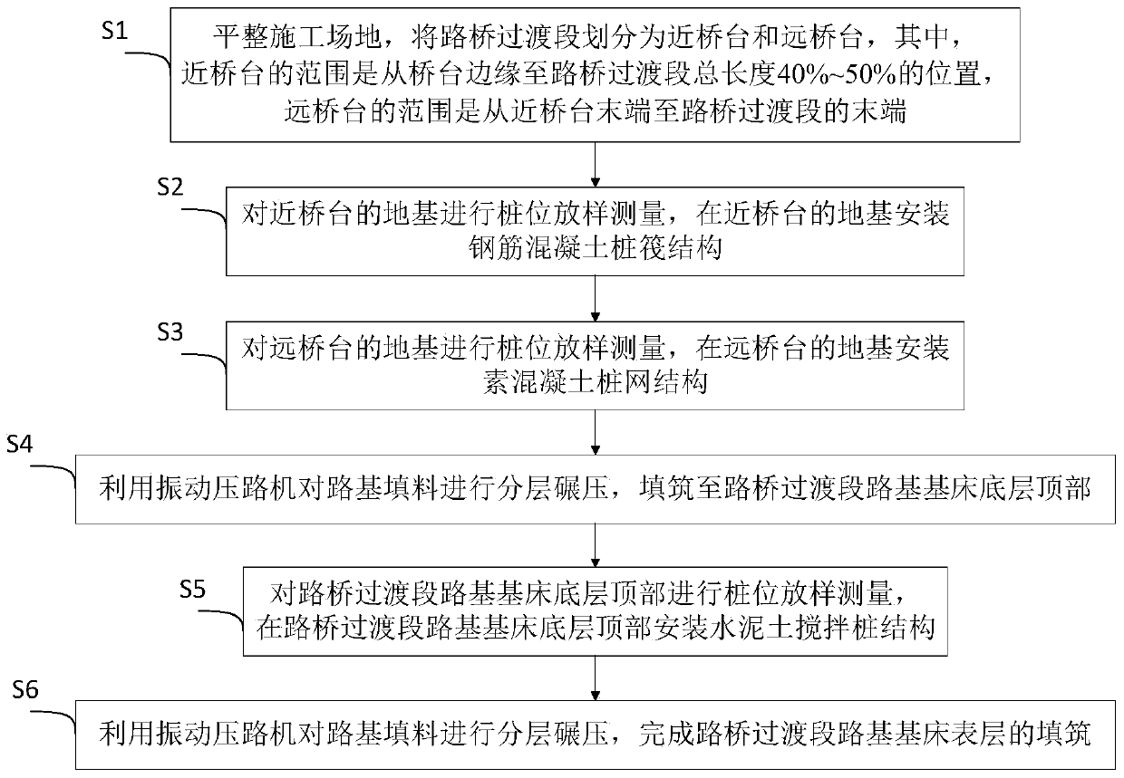
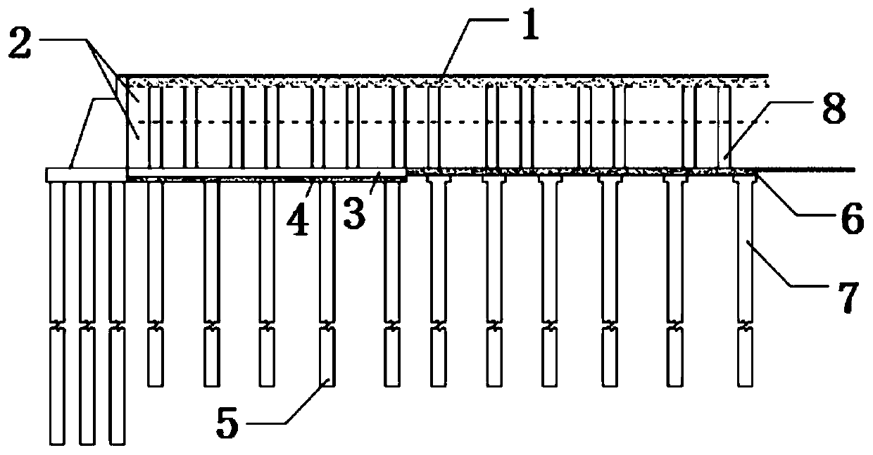
[0043] Such as figure 1 As shown, a pile composite structure construction method for controlling the uneven settlement of the high-speed railway bridge transition section includes the following steps:

[0044] S1. Leveling the construction site, dividing the road-bridge transition section into near abutment and far abutment, wherein the range of near abutment is 40%-50% of the total length from the edge of the abutment to the road-bridge transition section, and the area of ​​far abutment The range is from the end of the near abutment to the end of the road-bridge transition section;

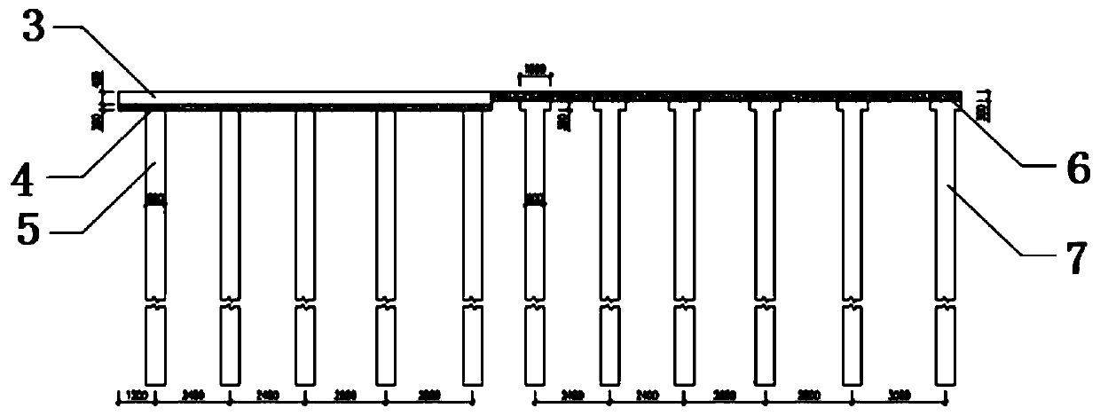
[0045] S2. Carry out stakeout measurement on the foundation near the abutment, and install a reinforced concrete pile raft structure on the foundation near the abutment;

[0046] S3. Carry out pile position stakeout measurement on the foundation of the far abu...


PUM


Abstract

The invention relates to a pile composite structure construction method for controlling differential settlement of a high-speed railway bridge transition section, which comprises the following steps:S1, leveling a construction site, and dividing the high-speed railway bridge transition section into a near abutment and a far abutment; s2, installing a reinforced concrete piled raft structure on the foundation close to the bridge abutment; s3, installing a plain concrete pile net structure on the foundation far away from the bridge abutment; s4, rolling the roadbed filler layer by layer, and filling the filler to the top of the roadbed bed bottom layer of the road and bridge transition section; s5, mounting a cement mixing pile structure at the top of the bottom layer of the roadbed bed ofthe road and bridge transition section; and S6, completing the filling of the roadbed surface layer of the road and bridge transition section. Compared with the prior art, the cement mixing piles on the roadbed are combined with the reinforced concrete piled raft structure and the plain concrete piled net structure on the foundation treatment; by combining the longitudinal pile spacing with transition change, longitudinal differential settlement of the road and bridge transition section can be effectively controlled, rigid transition can be realized without filling of a forward trapezoidal roadbed and an inverted trapezoidal roadbed, and the construction quality is ensured.

Description

technical field [0001] The invention relates to the technical field of high-speed railway construction, in particular to a pile composite structure construction method for controlling uneven settlement of transition sections of high-speed railway bridges. Background technique [0002] With the continuous advancement of railway technology, it will be the future development trend to continue to increase the speed of passenger trains and increase the transport capacity of freight trains. For high-speed railways, setting up road-bridge transition sections at the junction of roadbeds and bridges can gradually change the track stiffness. When the train passes at high speed, it can reduce the vibration of the train and the line, thereby slowing down the deformation of the line structure. Therefore, the road-bridge transition section is a key link in the design and construction of high-speed railways. [0003] However, the road-bridge transition section also restricts the further sp...

Claims


Application Information

Patent Timeline
Patent Type & Authority Applications(China)
IPC IPC(8): E01B2/00E02D5/46
CPCE01B2/006E02D5/46
Inventor 周顺华王炳龙王长丹张博刘琤玉
Owner TONGJI UNIV
Why Eureka
Try Eureka