Supercharge Your Innovation With Domain-Expert AI Agents!

A Multi-Oil Channel Fuel Spray Device Applicable to Radially Staged Main Combustion Chamber

A spray device and main combustion chamber technology, applied in the field of aero-engines, can solve problems such as increased number of nozzles, bloated fuel system, difficulties in combustion chamber ignition and flame transfer, and flame stabilization, achieving simplified fuel system, compact internal structure, and weight saving Effect

Active Publication Date: 2021-08-03
AECC SICHUAN GAS TURBINE RES INST
View PDF0 Cites 0 Cited by
  • Summary
  • Abstract
  • Description
  • Claims
  • Application Information

AI Technical Summary

Problems solved by technology

In the future, the flight altitude and flight Mach number of the engine envelope will be further improved. At the same time, considering the flow capacity requirements of the engine under the temperature limit, the cross-sectional flow velocity of the combustion chamber has approached the professional design criteria, and the fuel supply under the conventional dual oil supply design is adopted. The range of change is beyond the supply capacity of the existing fuel pump, and the size of the combustion chamber is far beyond the existing conventional combustion chamber; making it difficult for the combustion chamber to efficiently organize combustion in a wide range, to ignite and transfer flames, and to stabilize the flame
The radially graded main combustion chamber can be effectively solved by adopting the flame cylinder in the form of a double-annular cavity structure and the fuel supply scheme of three oil channels for graded fuel supply; but using the above-mentioned technical scheme, such as using traditional structure nozzles, the number of nozzles will be doubled , causing the fuel system to be too bloated, causing certain difficulties in installation and maintenance; at the same time, the temperature at the inlet of the combustion chamber continues to rise under the condition of high altitude and high Mach number. If reasonable measures are not taken, the temperature of the fuel in the fuel nozzle will rise. The thermal protection design of the nozzle device further increases the structural complexity of the nozzle device

Method used


Image

  • A Multi-Oil Channel Fuel Spray Device Applicable to Radially Staged Main Combustion Chamber
  • A Multi-Oil Channel Fuel Spray Device Applicable to Radially Staged Main Combustion Chamber
  • A Multi-Oil Channel Fuel Spray Device Applicable to Radially Staged Main Combustion Chamber

Examples


Embodiment Construction

[0023] In order to make the object, technical solution and advantages of the present invention clearer, the present invention will be described in further detail below in conjunction with specific embodiments and with reference to the accompanying drawings.

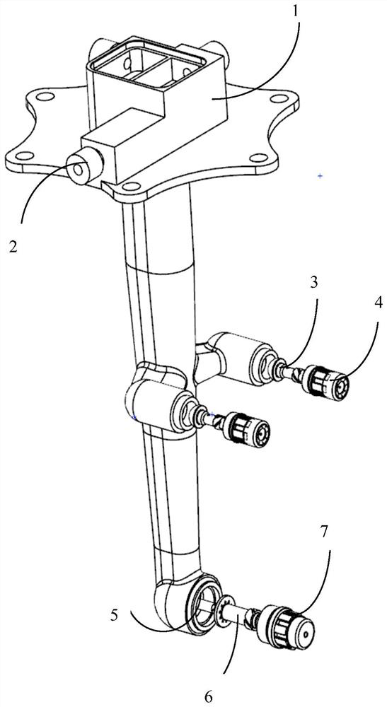
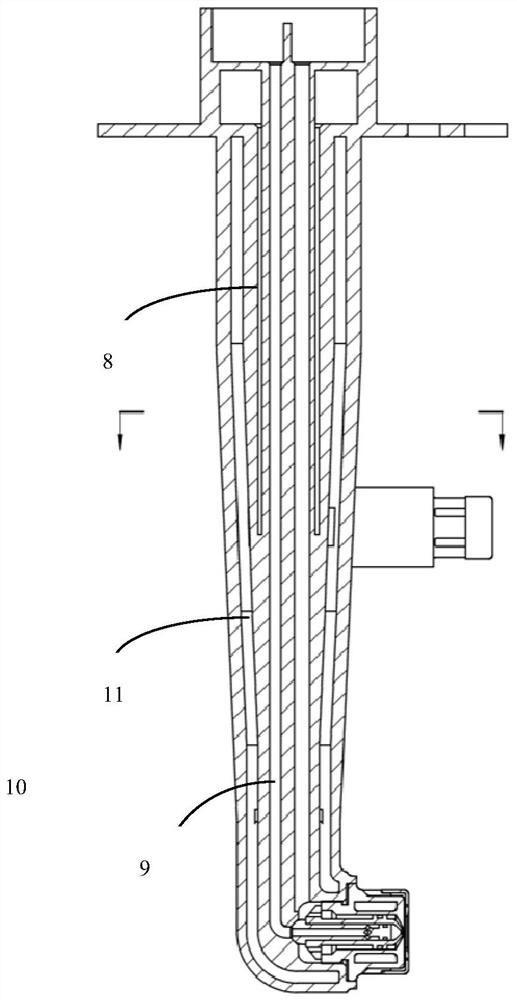
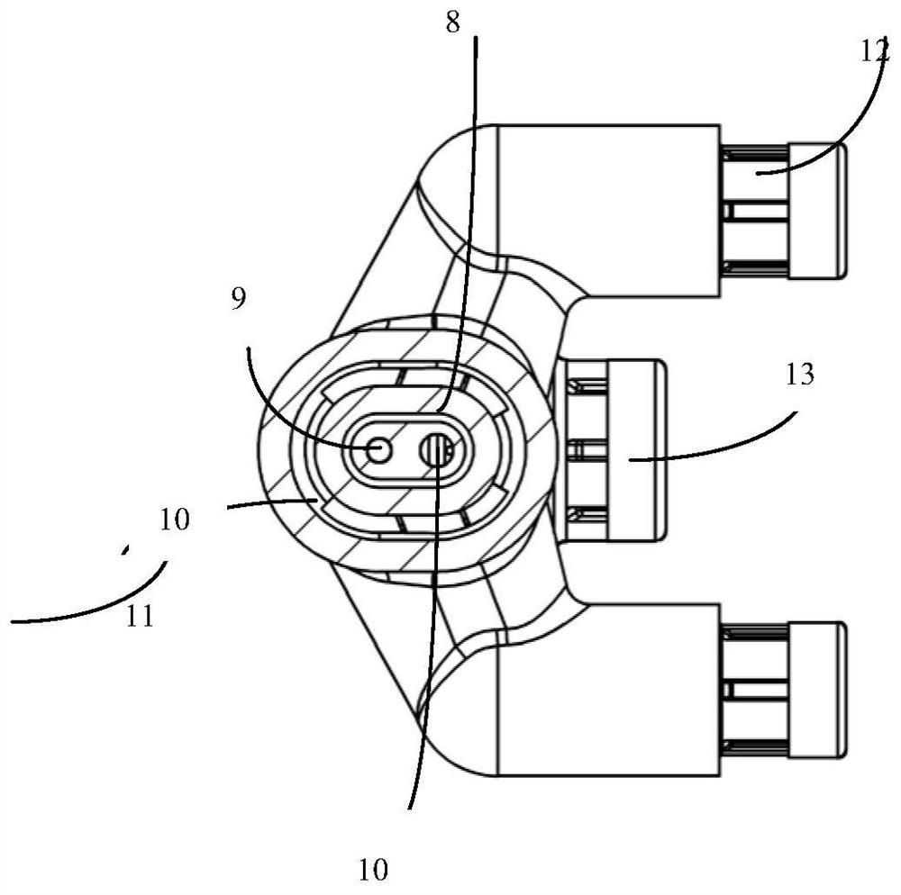
[0024] refer to figure 1 , a multi-oil channel fuel spray device suitable for radially graded main combustion chambers adopts the form of partitioned fuel supply, and the two pre-combustion stage nozzles 12 located on the radially graded outer ring are single oil circuit nozzles, located on the radially graded inner ring The main combustion stage nozzle 13 is a dual oil circuit nozzle. The pre-combustion level nozzles 12 and the main combustion level nozzles are installed on the spray device housing 1 through threads 13, and the two pre-combustion level nozzles 12 are symmetrically distributed on the center section of the spray device housing 1. The three oil inlet nozzles 2 located above the spray device housing 1 are r...


PUM


Abstract

The patent of the present invention relates to a multi-oil fuel spray device suitable for radially graded main combustion chambers, including a spray device housing, a pre-combustion nozzle, and a main combustion nozzle. The pre-combustion nozzle and the main combustion nozzle Installed on the housing of the spray device, the main combustion stage nozzle is located in the radially graded inner ring, and the pre-combustion stage nozzle is located in the radially graded outer ring; the present invention integrates the three nozzles through the multi-head design As a whole, the fuel system is simplified and the weight is saved; at the same time, by optimizing the layout of the oil circuit, the internal structure of the nozzle housing is made more compact, so that the integrated air insulation layer can provide heat protection for the main flow of the entire oil circuit.

Description

technical field [0001] The invention belongs to the technical field of aero-engines, and relates to a multi-oil channel fuel spraying device suitable for a radially graded main combustion chamber. Background technique [0002] The fuel nozzle is an important part in the main combustion chamber of an aero-engine. Its main function is to atomize the fuel, spray it into the combustion chamber and mix it with air for combustion. With the expansion of the flight envelope of the aero-engine, the fuel-air ratio of the combustion chamber becomes larger, and the fuel flow range becomes wider and wider. Therefore, the fuel nozzles of the modern aero-engine combustors are generally designed with dual oil circuits to meet the wide range of fuel flow. . In the future, the flight altitude and flight Mach number of the engine envelope will be further improved. At the same time, considering the flow capacity requirements of the engine under the temperature limit, the cross-sectional flow v...

Claims


Application Information

Patent Timeline
Patent Type & Authority Patents(China)
IPC IPC(8): F23R3/28F23R3/34F23R3/38
CPCF23R3/283F23R3/346F23R3/38
Inventor 陈浩范珍涔邓远灏袁昌波郭凯曾宇晖黄阿勇李朋玉
Owner AECC SICHUAN GAS TURBINE RES INST
Features
  • R&D
  • Intellectual Property
  • Life Sciences
  • Materials
  • Tech Scout
  • Unparalleled Data Quality
  • Higher Quality Content
  • 60% Fewer Hallucinations
Learn More