
Clamping device in high-precision optical element interference detection

An optical element, interference detection technology, applied in the direction of using optical devices, measuring devices, optical instrument testing, etc., can solve problems such as uneven clamping force, affecting detection accuracy, etc., to improve uniformity, reduce deformation, and stabilize positioning. Effect

Pending Publication Date: 2020-04-03
LASER FUSION RES CENT CHINA ACAD OF ENG PHYSICS
View PDF0 Cites 3 Cited by
  • Summary
  • Abstract
  • Description
  • Claims
  • Application Information

AI Technical Summary

Problems solved by technology

[0005] For this reason, an object of the present invention is to propose a clamping device in the interference detection of high-precision optical components, which solves the technical problem of uneven clamping force in the detection of optical detection components in the prior art and affects the detection accuracy

Method used


Image

  • Clamping device in high-precision optical element interference detection
  • Clamping device in high-precision optical element interference detection
  • Clamping device in high-precision optical element interference detection

Examples


Embodiment Construction

[0028] Embodiments of the present invention are described in detail below, examples of which are shown in the drawings, wherein the same or similar reference numerals designate the same or similar elements or elements having the same or similar functions throughout. The embodiments described below by referring to the figures are exemplary and are intended to explain the present invention and should not be construed as limiting the present invention.

[0029] In describing the present invention, it is to be understood that the terms "upper", "lower", "front", "rear", "left", "right", "vertical", "horizontal", "top", The orientation or positional relationship indicated by "bottom", "inner", "outer", etc. is based on the orientation or positional relationship shown in the drawings, and is only for the convenience of describing the present invention and simplifying the description, rather than indicating or implying the referred device or positional relationship. Elements must hav...


PUM

PropertyMeasurementUnit
Thicknessaaaaaaaaaa

Abstract

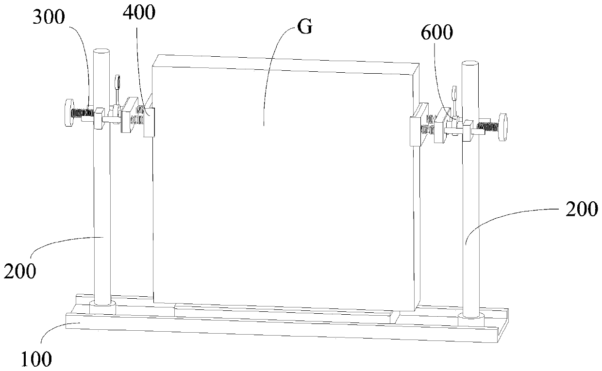
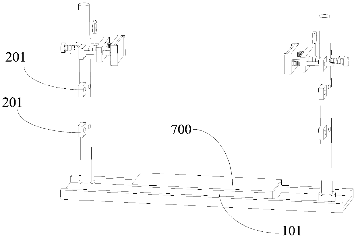
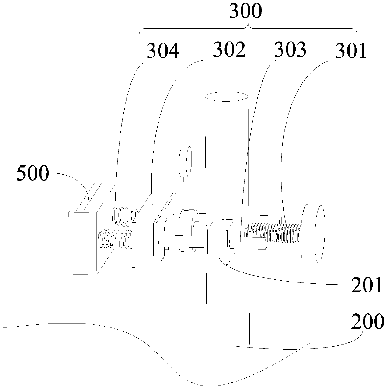
The invention relates to a clamping device in high-precision optical element interference detection. The clamping device comprises a base, and the two sides of the base are each provided with a groupof supporting columns. One side of each group of connecting pushing parts is connected with the supporting columns, and the other side of each group of connecting pushing parts is correspondingly connected with one group of clamping parts. The two groups of clamping parts do clamping or loosening motion along the opposite directions, each group of clamping parts is provided with an elastic piece abutting against the side face of an optical element, and a force sensor is fixed on the connection pushing parts and is used for measuring the counter-acting force of the clamping parts on the clamping force of the optical element. The optical element is clamped through the base and the clamping parts at the two sides, so that the clamping stability of the optical element is guaranteed. The elastic piece is beneficial to improving the uniformity of the clamping force of the clamping parts on the optical element, and therefore the deformation of the optical element and the influence of the deformation on the detection precision are reduced. The force sensor is used for measuring the counter-acting force of the clamping part on the clamping force of the optical element, and a reference for adjusting the clamping force in the clamping process is provided.

Description

technical field [0001] The invention relates to the technical field of optical element detection auxiliary devices, and more specifically relates to a clamping device for high-precision optical element interference detection. Background technique [0002] Optical interferometer is a precision measuring instrument based on the principle of light interference to measure the surface error of optical components. In the optical interferometer, the monochromatic light emitted by the laser becomes parallel light after passing through the collimating objective lens in the optical path, and then the beam is split and projected to the reference mirror and the optical element under test, and the optical element is obtained by solving the interference fringes of the reference beam and the test beam surface error. When the optical interferometer is used to detect the surface error of the high-precision optical element, the optical element is clamped and held by the inspection fixture, t...

Claims


Application Information

Patent Timeline
IPC IPC(8): G01B11/24G01M11/02
CPCG01B11/2441G01M11/0271
Inventor 廖德锋谢瑞清赵世杰侯晶陈贤华刘民才王健许乔
Owner LASER FUSION RES CENT CHINA ACAD OF ENG PHYSICS
Learn More