Cooling system of oil-immersed self-cooling transformer

A transformer, oil-immersed technology, applied in the field of transformer cooling, can solve problems such as poor heat dissipation capacity

Inactive Publication Date: 2020-04-03
GUANGAN POWER SUPPLY COMPANY STATE GRID SICHUANELECTRIC POWER
View PDF18 Cites 0 Cited by
  • Summary
  • Abstract
  • Description
  • Claims
  • Application Information

AI Technical Summary

Problems solved by technology

[0003] The purpose of the present invention is to provide a cooling system for oil-immersed self-cooling transformers to solve the problems in the prior art that oil-immersed self-cooling transformers have poor heat dissipation capability and long-term high-temperature alarm state, and achieve the purpose of reducing manpower consumption and improving heat dissipation efficiency

Method used


Image

  • Cooling system of oil-immersed self-cooling transformer
  • Cooling system of oil-immersed self-cooling transformer
  • Cooling system of oil-immersed self-cooling transformer

Examples


Embodiment 1

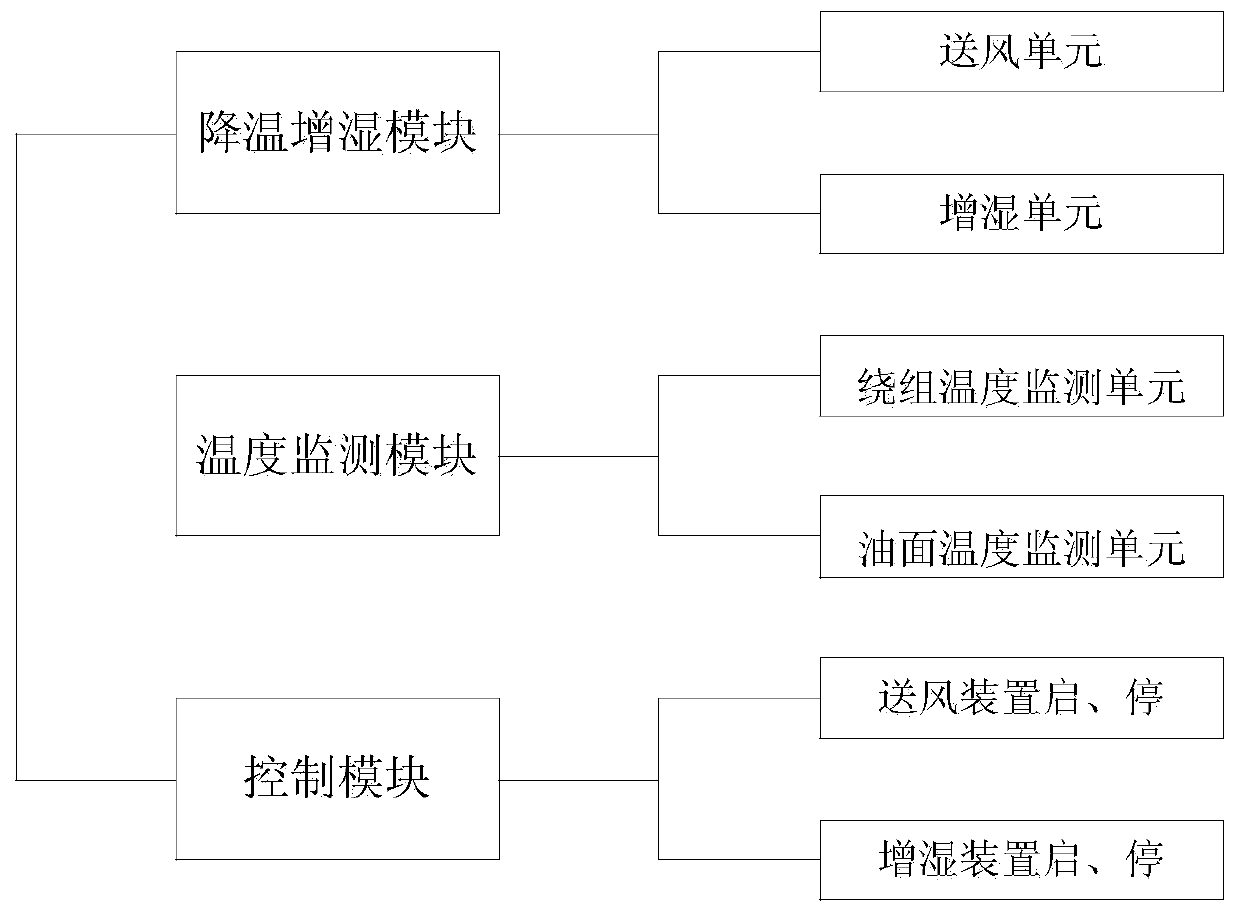
[0029] Such as figure 1 and figure 2 An oil-immersed self-cooling transformer cooling system is shown, which is characterized in that it includes a winding temperature monitoring unit, an oil surface temperature monitoring unit, a humidification unit, an air supply unit, and a control module. The control module is based on the winding temperature monitoring unit. The signal controls the start and stop of the humidification unit, and the control module controls the start and stop of the air supply unit according to the signal of the oil surface temperature monitoring unit. The winding temperature monitoring unit and the oil surface temperature monitoring unit are respectively the winding temperature controller and the oil surface temperature controller of the oil-immersed self-cooling transformer.

[0030] Preferably, the control module includes two groups of control units, and the two groups of control units respectively control the start and stop of the humidification unit ...

Embodiment 2

[0032] Such as figure 1 and figure 2 A kind of oil-immersed self-cooling transformer cooling system shown, on the basis of embodiment 1:

[0033] The start and stop of the humidifying unit respectively correspond to the temperatures A and B monitored by the winding temperature monitoring unit;

[0034] The start and stop of the air supply unit correspond to the temperatures C and D monitored by the oil surface temperature monitoring unit respectively;

[0035] Among them, A>C>B>D.

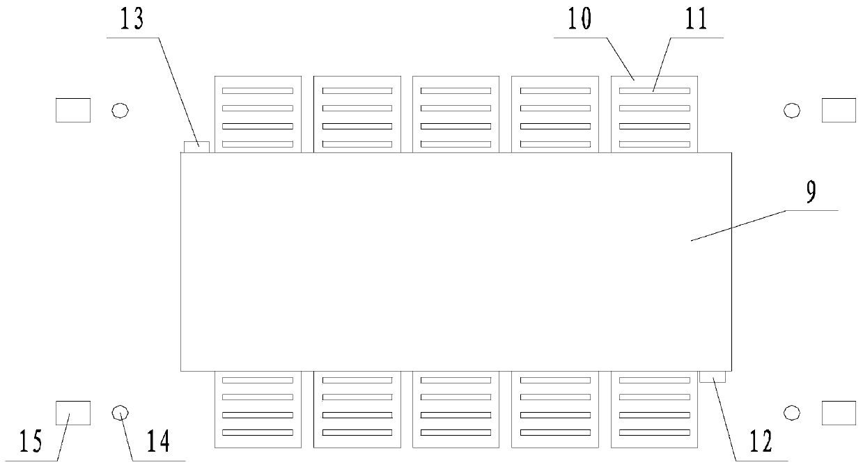
[0036] A number of humidification units and air supply units are arranged around the transformer, and each air supply unit is matched with a humidification unit; the air supply unit is located on the side of the corresponding humidification unit away from the heat sink of the transformer. The connection line between each air supply unit and the corresponding humidification unit is perpendicular to the connection line between the cooling fins.

[0037] In this embodiment, when the temperature m...

Embodiment 3

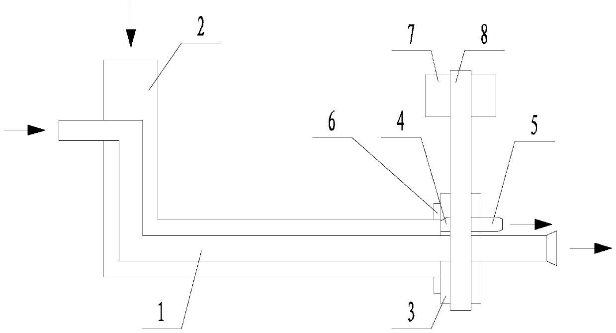
[0047] Such as Figure 1 to Figure 3 An oil-immersed self-cooling transformer cooling system shown is based on any of the above-mentioned embodiments: the humidification unit includes a water inlet pipe 1, and the air supply unit includes an air inlet pipe 2, and the water inlet pipe 1 is from The side wall of the intake pipe 2 is inserted into the intake pipe 2, and passes through the outlet end of the intake pipe 2, and also includes a turntable 3 that is sleeved on the water inlet pipe 1, and the turntable 3 is closed to the outlet end of the intake pipe 2 , the turntable 3 is provided with a channel 4 communicating with the air intake pipe 2 , and also includes an air gathering port 5 communicating with the channel 4 . The end of the intake pipe 2 adjacent to the turntable 3 is fixedly sleeved with a sealing ring 6 . The rotation connection between the rotating disk 3 and the water inlet pipe 1 is realized through a bearing. It also includes a driving mechanism for drivi...


PUM


Abstract

The invention discloses a cooling system of an oil-immersed self-cooling transformer. The system comprises a winding temperature monitoring unit, an oil surface temperature monitoring unit, a humidifying unit, an air supply unit and a control module, the control module controls starting and stopping of the humidifying unit according to signals of the winding temperature monitoring unit, and the control module controls starting and stopping of the air supply unit according to signals of the oil surface temperature monitoring unit. The invention aims to provide the cooling system for the oil-immersed self-cooling transformer, so as to solve the problems that the oil-immersed self-cooling transformer in the prior art is poor in heat dissipation capability and is in a high-temperature alarm state for a long time, and achieve the purposes of reducing manpower consumption and improving heat dissipation efficiency.

Description

technical field [0001] The invention relates to the field of transformer cooling, in particular to an oil-immersed self-cooling transformer cooling system. Background technique [0002] According to the heat dissipation principle of oil-immersed natural air-cooled transformers, the heat dissipation mechanism of this method is mainly through the temperature difference between the inside and outside of the transformer (the temperature in the transformer near the winding and iron core is high, and the external environment temperature of the transformer is low) and the large specific heat of the transformer oil. , so that the transformer oil close to the iron core and winding is heated and expanded during normal operation of the transformer, and the up and down convection of the oil makes the transformer oil dissipate the heat in time through the heat sink, thereby ensuring the normal operation of the transformer. At present, in the power grid system, more and more natural air-c...

Claims


Application Information

Patent Timeline
IPC IPC(8): H01F27/08H01F27/18H01F27/22H01F27/40
CPCH01F27/085H01F27/18H01F27/22H01F27/40H01F27/402H01F2027/406
Inventor 刘秀峰殷作洋龚妮凃斌周劲沈大千何军吴应林郭志荣廖晓琴康蓝心莫钦森熊明李顺柯小会马子威罗高王淦朱绍铁
Owner GUANGAN POWER SUPPLY COMPANY STATE GRID SICHUANELECTRIC POWER
Why Eureka
Try Eureka