
Commutation point position correction method of sensorless brushless direct current motor based on terminal voltage method

A brushed DC motor and correction method technology, applied in electronic commutation motor control, electrical components, control systems, etc., can solve problems such as poor practicability, achieve good practicability, ensure accurate commutation, and be beneficial to engineering applications.

Active Publication Date: 2020-04-03
NORTHWESTERN POLYTECHNICAL UNIV
View PDF3 Cites 3 Cited by
  • Summary
  • Abstract
  • Description
  • Claims
  • Application Information

AI Technical Summary

Problems solved by technology

[0006] In order to overcome the shortcomings of the poor practicability of the existing sensorless brushless DC motor commutation point position correction method, the present invention provides a position sensorless brushless DC motor commutation point position correction method based on the terminal voltage method

Method used


Image

  • Commutation point position correction method of sensorless brushless direct current motor based on terminal voltage method
  • Commutation point position correction method of sensorless brushless direct current motor based on terminal voltage method
  • Commutation point position correction method of sensorless brushless direct current motor based on terminal voltage method

Examples


Embodiment Construction

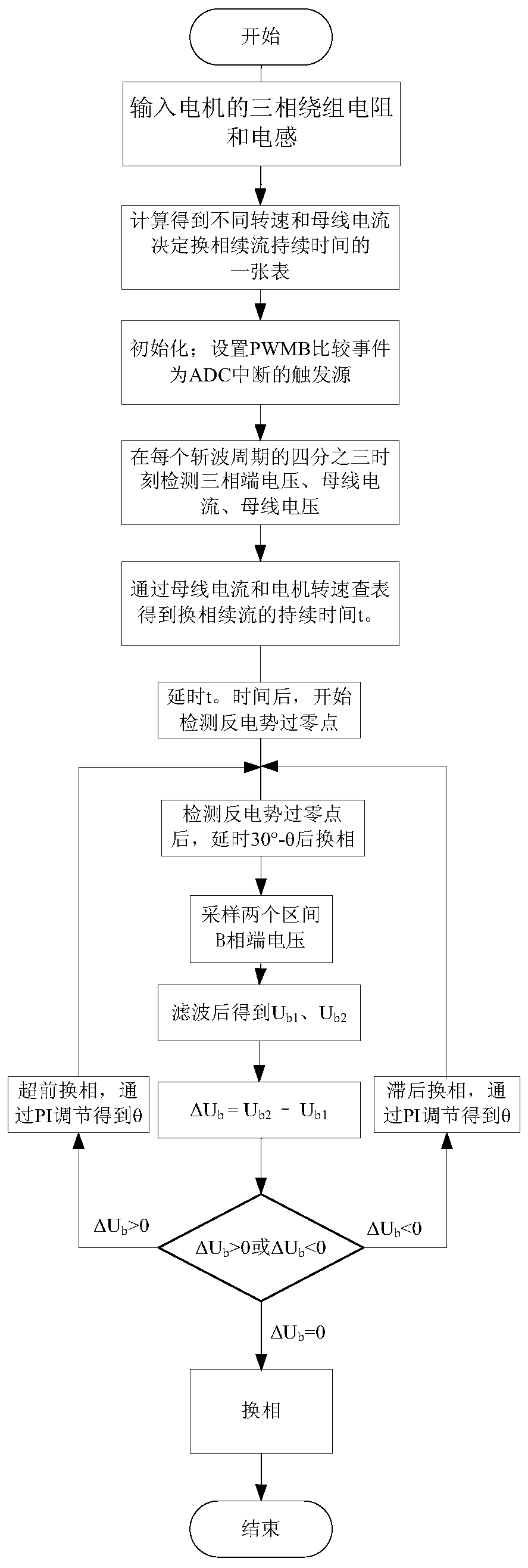
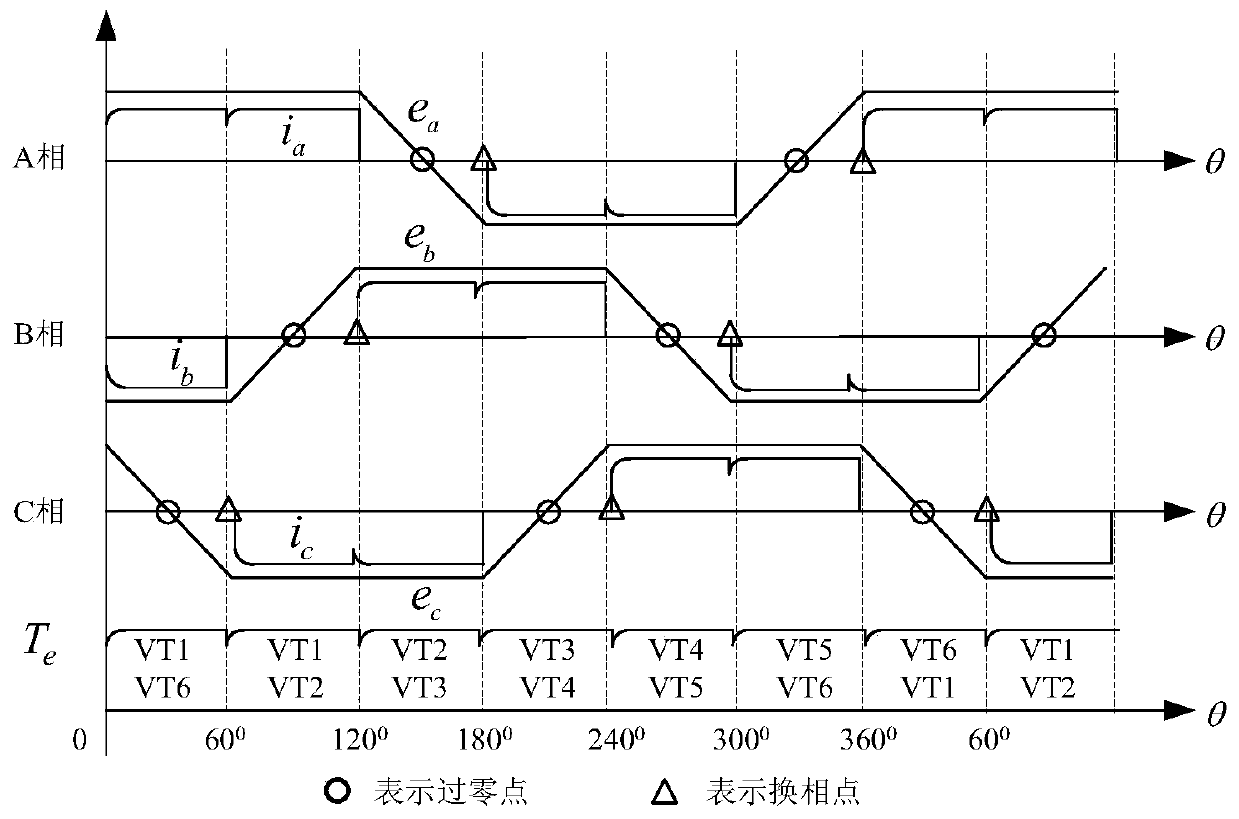
[0028] The following examples refer to Figure 1-2 , 4, 9-12.

[0029] The most commonly used drive circuit for brushless DC motors is a three-phase full-bridge power inverter circuit composed of six power tubes, which is divided into three bridge arms, each bridge arm is composed of upper and lower power tubes. The midpoint of each bridge arm is connected to one-phase winding of the three-phase motor, that is, the Y-shaped connection method. By changing the switching state of each switching tube, the phase commutation of the brushless DC motor can be realized.

[0030] During normal operation, the conduction interval of the phase current of the brushless DC motor should be in phase with the flat-top interval of the back EMF waveform in order to generate a constant electromagnetic torque. The commutation point of the brushless DC motor can be estimated based on the zero-crossing point of the non-conducting opposite potential waveform and the time delay of 30° electrical angle...


PUM


Abstract

The invention discloses a commutation point position correction method of a sensorless brushless direct current motor based on a terminal voltage method. The correction method is used for solving thetechnical problem of poor practicability of the existing commutation point position correction method of the sensorless brushless direct current motor. According to the technical scheme, by detectingthe terminal voltage in real time, waveform symmetry of the terminal voltage is kept, correction of a commutation point of the motor is achieved, accurate commutation of the motor is guaranteed, the operation performance of the motor is improved, and advance or lag commutation and out-of-step faults of the motor are prevented. According to the invention, no extra circuit is needed, and the hardware cost of the system is not increased. Complex mathematical and logical calculation does not need to be carried out in software, and the requirement for the calculation speed of the microprocessor isnot too high. Therefore, implementation is easy, and engineering application is facilitated. The method is not only suitable for a high-voltage high-power brushless direct current motor control system, but also suitable for other brushless direct current motor control systems, and is good in practicability.

Description

technical field [0001] The invention relates to a method for correcting the position of a commutation point of a brushless direct current motor without a position sensor, in particular to a method for correcting the position of a commutation point of a brushless direct current motor without a position sensor based on a terminal voltage method. Background technique [0002] Brushless DC motor (BLDCM) not only has the advantages of simple control and good speed regulation performance of DC motor, but also has the advantages of reliable operation and convenient maintenance of AC motor, so its application range covers aviation, aerospace, transportation, home appliances and many other fields. [0003] However, the rotor position sensor is the component with the highest failure probability of the brushless DC motor, which not only reduces the reliability of the brushless DC motor, increases the cost of the motor, but also increases the volume of the motor. Therefore, the brushles...

Claims


Application Information

Patent Timeline
IPC IPC(8): H02P6/182
CPCH02P6/182
Inventor 马瑞卿张煜辰彭家勇李添幸
Owner NORTHWESTERN POLYTECHNICAL UNIV
Learn More