
Pump head, pressure pump and pressure pump control method

A technology of pressure pumps and pump heads, which is applied in the field of medical equipment, can solve the problems of high stability requirements of circuit electrical equipment, achieve the effect of reducing the cost of electrical equipment, reducing the requirements of control accuracy, and improving stability

Pending Publication Date: 2020-04-07
MICRO TECH (NANJING) CO LTD
View PDF0 Cites 1 Cited by
  • Summary
  • Abstract
  • Description
  • Claims
  • Application Information

AI Technical Summary

Problems solved by technology

[0002] In the interventional medical process, the precision of the pressure pump liquid infusion is high, and the electronic control method is usually used in the prior art to realize the technical problem of ensuring the smooth flow rate of the liquid during the piston steering process. The defect of this method is that the electronic The control accuracy is high, and whether the liquid flow rate can be stabilized depends on the precise control of the electronic equipment, so the accuracy of the circuit and the stability of the electrical equipment are high.

Method used


Image

  • Pump head, pressure pump and pressure pump control method
  • Pump head, pressure pump and pressure pump control method
  • Pump head, pressure pump and pressure pump control method

Examples


Embodiment Construction

[0065] In order to make the purpose, technical solutions and advantages of the embodiments of the present invention clearer, the technical solutions in the embodiments of the present invention will be clearly and completely described below in conjunction with the drawings in the embodiments of the present invention. Obviously, the described embodiments It is a part of embodiments of the present invention, but not all embodiments. The components of the embodiments of the invention generally described and illustrated in the figures herein may be arranged and designed in a variety of different configurations.

[0066] Accordingly, the following detailed description of the embodiments of the invention provided in the accompanying drawings is not intended to limit the scope of the claimed invention, but merely represents selected embodiments of the invention. Based on the embodiments of the present invention, all other embodiments obtained by persons of ordinary skill in the art wi...


PUM


Abstract

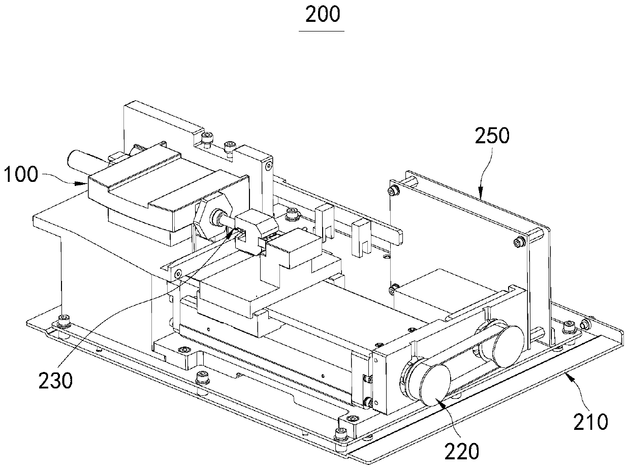
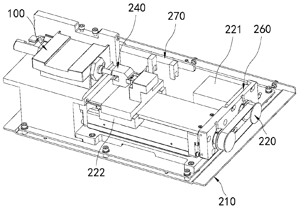
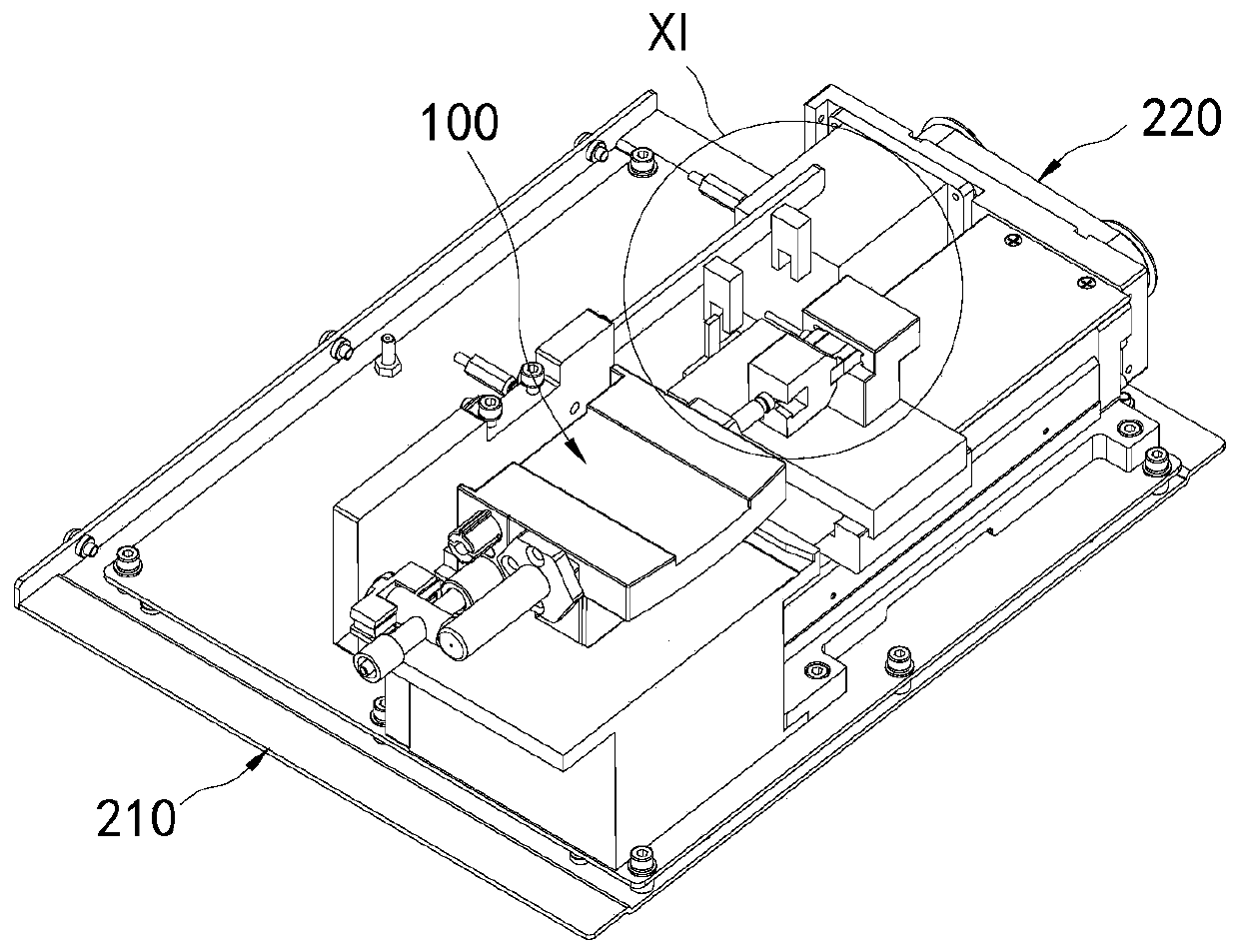
The invention relates to the technical field of medical instruments, in particular to a pump head, a pressure pump and a pressure pump control method. The pump head comprises a pump body, a piston, apiston rod and an expandable first pressure stabilizing pipe. The piston and the piston rod are located in the inner cavity of the pump body, the piston is connected with the piston rod and attached to the wall of the inner cavity, and the piston rod is used for driving the piston to reciprocate relative to the inner cavity in the preset direction. The piston divides the inner cavity into a firstchamber and a second chamber; the pump body is provided with a first liquid outlet correspondingly communicated with the first cavity and a second liquid outlet correspondingly communicated with the second cavity. The first liquid outlet and the second liquid outlet are both communicated with one end of the first pressure stabilizing tube, and the other end of the first pressure stabilizing tube is used for being communicated with a surgical instrument; and the first pressure stabilizing tube is used for switching between an expansion state and a contraction state so as to compensate the pressure of the liquid in the first pressure stabilizing tube and reduce the flow change when the first pressure stabilizing tube continuously conveys the liquid to the surgical instrument. Stable liquid infusion can be ensured.

Description

technical field [0001] The invention relates to the technical field of medical devices, in particular to a pump head, a pressure pump and a pressure pump control method. Background technique [0002] In the interventional medical process, the precision of the pressure pump liquid infusion is high, and the electronic control method is usually used in the prior art to realize the technical problem of ensuring the smooth flow rate of the liquid during the piston steering process. The defect of this method is that the electronic The control accuracy is high, and whether the liquid flow rate can be stabilized depends on the precise control of the electronic equipment, so the accuracy of the circuit and the stability of the electrical equipment are high. Contents of the invention [0003] The object of the present invention includes providing a pump head, a pressure pump and a pressure pump control method, which can reduce the requirements on the control accuracy of electrical e...

Claims


Application Information

Patent Timeline
IPC IPC(8): F04B53/16F04B17/03F04B49/10A61M5/142
CPCF04B53/16F04B17/03F04B49/10A61M5/14216A61M2205/33
Inventor 刘辉庞金伟冷德嵘李常青奚杰峰李宁刘春俊唐志韦建宇
Owner MICRO TECH (NANJING) CO LTD
Learn More