A split brake and motor

A brake and split technology, applied in the direction of brake type, axial brake, brake actuator, etc., can solve the problems affecting the reliability of the encoder 3, abnormal communication, etc., and achieve the effect of simple and reliable process and improved reliability.

Active Publication Date: 2021-04-27
GREE ELECTRIC APPLIANCES INC +1
View PDF5 Cites 0 Cited by
  • Summary
  • Abstract
  • Description
  • Claims
  • Application Information

AI Technical Summary

Problems solved by technology

Since the encoder 3 needs to work in a dust-free environment, the encoder 3 with dust attached will have abnormal communication, which directly affects the reliability of the encoder 3 operation

Method used


Image

  • A split brake and motor
  • A split brake and motor
  • A split brake and motor

Examples


Embodiment 1

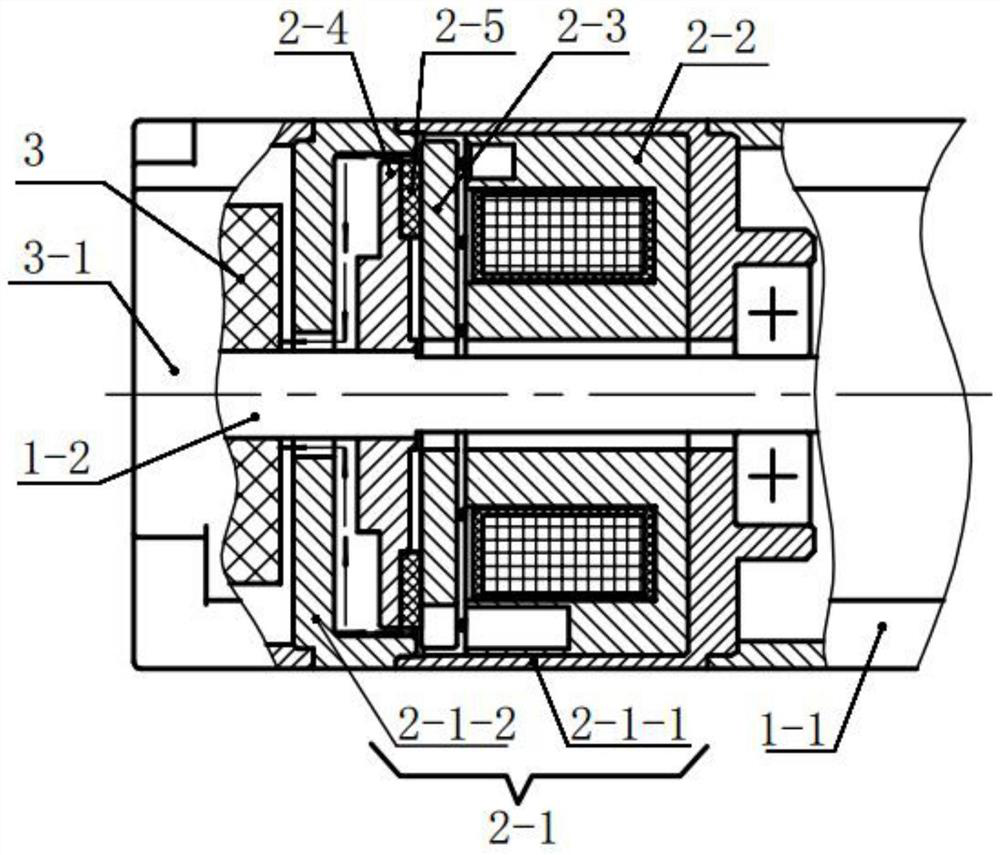
[0037] The split brake of the first embodiment is installed on the non-shaft extension end of the motor, and the encoder 3 is installed on the end of the split brake of the first embodiment away from the motor.

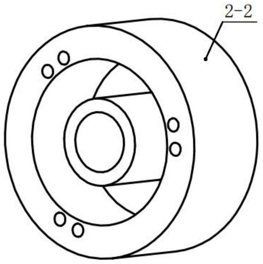
[0038] A split type brake of the first embodiment, such as image 3 As shown, it includes a housing 2-1 of the brake, a brake iron core 2-2, an armature 2-3, a wheel hub 2-4, and a friction plate 2-5.

[0039] The housing 2-1 of the brake includes a first end cover 2-1-1 and a second end cover 2-1-2, and the first end cover 2-1-1 and the second end cover 2-1-2 are fixed by screws . The first end cover 2-1-1 is fixed with the housing 1-1 of the motor by screws, and the second end cover 2-1-2 is in clearance fit with the rotating shaft 1-2 of the motor.

[0040] The brake iron core 2-2, the armature 2-3, the wheel hub 2-4 and the friction plate 2-5 are all arranged in the first end cover 2-1-1.

[0041] The brake iron core 2-2 is tightly fitted with the first end cov...

Embodiment 2

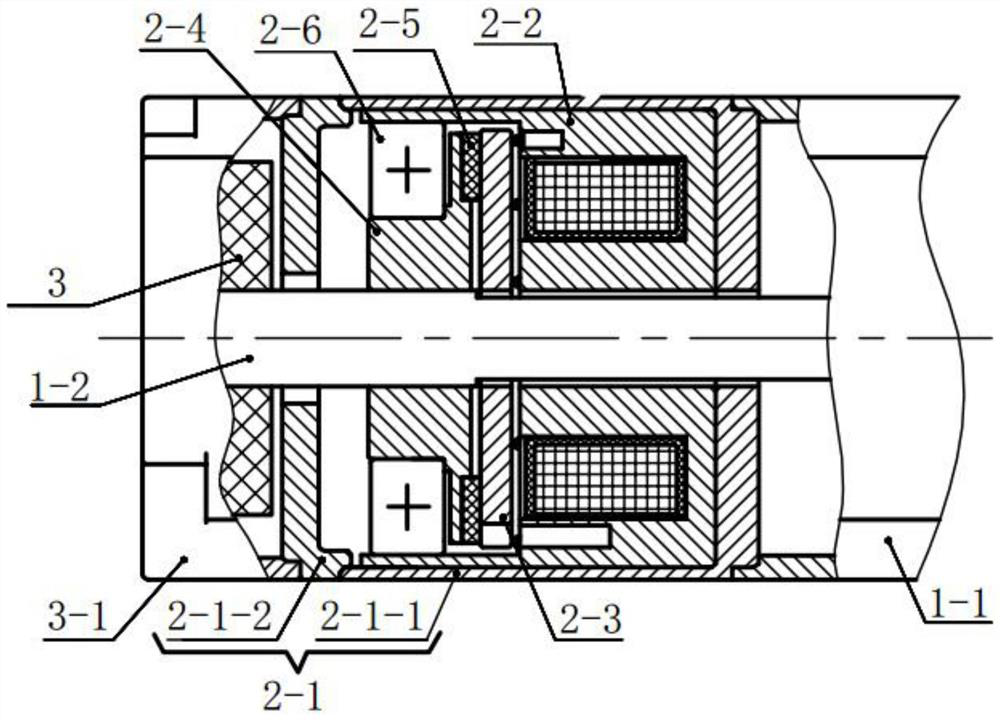
[0047] The split brake of the second embodiment is installed on the non-shaft extension end of the motor, and the encoder 3 is installed on the end of the split brake of the second embodiment away from the motor.

[0048] A split type brake of the second embodiment, such as Figure 5 As shown, it includes a housing 2-1 of the brake, a brake iron core 2-2, an armature 2-3, a wheel hub 2-4, and a friction plate 2-5.

[0049] The housing 2-1 of the brake includes a first end cover 2-1-1 and a second end cover 2-1-2, and the first end cover 2-1-1 and the second end cover 2-1-2 are fixed by screws . The first end cover 2-1-1 is fixed with the housing 1-1 of the motor by screws, and the second end cover 2-1-2 is in clearance fit with the rotating shaft 1-2 of the motor.

[0050] The brake iron core 2-2, the armature 2-3, the wheel hub 2-4 and the friction plate 2-5 are all arranged in the first end cover 2-1-1.

[0051] The brake iron core 2-2 is tightly fitted with the first end...

Embodiment 3

[0055] A motor includes a brake, and the brake is the aforementioned split type brake. The brake can improve the reliability of the encoder 3 during operation, so that the encoder 3 can accurately measure the parameters of the motor during operation, thereby improving the reliability of the motor operation.


PUM


Abstract

The invention discloses a split brake and a motor. A split brake includes a brake iron core, an armature, a wheel hub and a friction plate arranged in a brake housing. The brake iron core is closely matched with the brake housing, and the armature passes through the The elastic part is connected with the brake core, and the hub for tight fit with the motor shaft is set on the side of the armature away from the brake core, the hub is tightly fitted with the brake core through the seal, and the friction plate is set on the side of the hub close to the armature , the friction plate is connected with the wheel hub; a motor includes a brake, and the brake is the split brake described above. A split brake can prevent dust from entering the encoder shell and adhering to the code disc of the encoder; a motor, through which the brake can improve the reliability of the encoder during operation, so that the encoder can accurately measure the operation of the motor Time parameters, thereby improving the reliability of the motor operation.

Description

technical field [0001] The invention relates to the technical field of brake dust prevention, in particular to a split type brake and a motor. Background technique [0002] The structure of the motor equipped with the split brake is as follows figure 1 As shown, the split brake is installed on the non-shaft extension end of the motor, and the encoder 3 is installed on the end of the split brake away from the motor. [0003] When the brake coil of the split brake is energized, the brake iron core 2-2 is magnetized by the magnetic field of the brake coil, and the armature 2-3 is attracted by the magnetized brake iron core 2-2. The armature 2-3 continuously compresses the spring used to connect the armature 2-3 and the brake iron core 2-2 and is close to the brake iron core 2-2, so that the armature 2-3 is separated from the friction plate 2-5 on the hub 2-4 , so that the motor runs normally. When the motor runs normally, the hub 2-4, the friction plate 2-5, and the encoder 3...

Claims


Application Information

Patent Timeline
Patent Type & Authority Patents(China)
IPC IPC(8): F16D55/02F16D65/18F16D65/00F16C35/06H02K7/102F16D121/20F16D131/00
CPCF16C35/06F16C2226/10F16C2361/45F16D55/02F16D65/0031F16D65/18F16D2055/0008F16D2121/20F16D2131/00H02K7/1023
Inventor 赵国平叶小奔陈飞龙刘娜曹希
Owner GREE ELECTRIC APPLIANCES INC
Why Eureka
Try Eureka