Intelligent laser washing system for wheel sets and bogies

A technology of laser cleaning and bogies, which is applied in the direction of cleaning methods and appliances, chemical instruments and methods, etc., can solve problems such as adhesion to the surface of the cleaned object, mechanical force damage, environmental pollution, etc., to reduce operation and maintenance costs , reduce the intensity of work, and solve the effect of environmental pollution problems

Pending Publication Date: 2018-08-24
德阳瑞方智能交通设备科技有限公司
View PDF0 Cites 6 Cited by
  • Summary
  • Abstract
  • Description
  • Claims
  • Application Information

AI Technical Summary

Problems solved by technology

The invention effectively solves the problems of environmental pollution caused by traditional chemical cleaning, mechanical force damages the surface of the object, cleaning medium adheres to the surface of the object to be cleaned, and personnel safety, improves the automation of the cleaning equipment, and reduces the workload of workers The operation intensity improves the ope

Method used


Image

  • Intelligent laser washing system for wheel sets and bogies

Examples


Example Embodiment

[0027] Example 1:

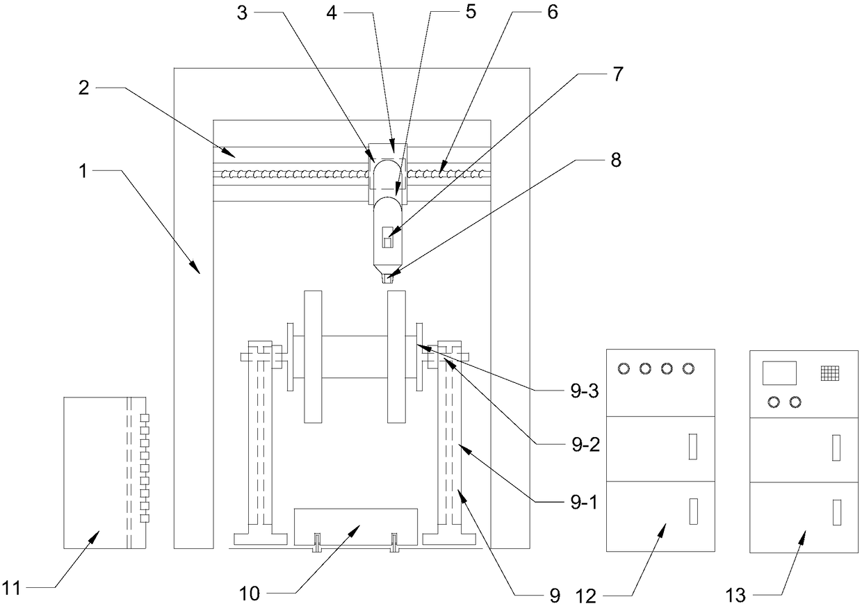
[0028] see figure 1 , an intelligent laser cleaning system for wheel sets and bogies, including a gantry 1, a horizontal linear rolling guide rail pair 2 and a horizontal ball screw pair 6, the moving parts of the rolling guide rail pair 2 are installed on the gantry frame 1 A fixed box 4 is fixed on the top, and a matching ball screw 3 is installed on the ball screw pair 6. The ball screw 3 is connected and fixed with the backboard of the robot 5 through the fixed box 4, and the machine between the elbow joint and the wrist joint of the robot 5 A machine vision system 7 is installed on the arm, and a laser head 8 is installed on the part below the robot 5 wrist joint.

[0029] In this example, the workpiece to be cleaned is transported to the recognizable range of the machine vision system 7, recognized by the machine vision system 7, the image signal is processed and displayed, and according to the display result, the ball screw on the ball screw pair 6 ...

Example Embodiment

[0030] Example 2:

[0031] see figure 1 , an intelligent laser cleaning system for wheel sets and bogies, including a gantry 1, a horizontal linear rolling guide rail pair 2 and a horizontal ball screw pair 6, the moving parts of the rolling guide rail pair 2 are installed on the gantry frame 1 A fixed box 4 is fixed on the top, and a matching ball screw 3 is installed on the ball screw pair 6. The ball screw 3 is connected and fixed with the backboard of the robot 5 through the fixed box 4, and the machine between the elbow joint and the wrist joint of the robot 5 A machine vision system 7 is installed on the arm, and a laser head 8 is installed on the part below the robot 5 wrist joint.

[0032]A workpiece fixing device 9 is arranged under the gantry 1, and the workpiece fixing device 9 is composed of two opposite pillars 9-1. A vertical lifting mechanism 9-2 is arranged inside the pillars 9-1, and a turning mechanism 9-2 is arranged on the vertical lifting mechanism 9-2. ...

Example Embodiment

[0034] Example 3:

[0035] see figure 1 , an intelligent laser cleaning system for wheel sets and bogies, including a gantry 1, a horizontal linear rolling guide rail pair 2 and a horizontal ball screw pair 6, the moving parts of the rolling guide rail pair 2 are installed on the gantry frame 1 A fixed box 4 is fixed on the top, and a matching ball screw 3 is installed on the ball screw pair 6. The ball screw 3 is connected and fixed with the backboard of the robot 5 through the fixed box 4, and the machine between the elbow joint and the wrist joint of the robot 5 A machine vision system 7 is installed on the arm, and a laser head 8 is installed on the part below the robot 5 wrist joint.

[0036] A section of rail groove is arranged on the ground below the gantry 1, and a workpiece transport vehicle 10 is installed on the rail groove. The bottom of the workpiece transport vehicle 10 is provided with rollers. The workpiece moves freely on the rail groove below the gantry 1 t...


PUM


Abstract

The invention relates to the field of rail traffic washing equipment, in particular to an intelligent laser washing system which is used for washing metal components such as wheels sets and bogies oftrucks, passenger cars, metros, bullet trains and locomotive inspection and repair bases. The intelligent laser washing system comprises a portal frame. A linear rolling guide rail pair and a horizontal ball screw pair are installed on the portal frame. A fixing box is fixed on a moving part of the rolling guide rail pair. A ball screw nut is installed on the ball screw pair. The ball screw nut isfixedly connected with a back plate of a robot through the fixing box. A machine vision system is installed on an arm of the robot. A laser head is installed on the portion under the wrist joints ofthe robot. According to the system, the automation degree is improved, working intensity of workers is reduced, operation efficiency is improved, a sewage treatment system is not needed, consumable items are not needed during operation, return on investment can be obtained fast, the operation and maintenance cost is reduced, long-distance operation is achieved, the parts which cannot be reached easily through the traditional washing method can be washed, and the system is suitable for being popularized in the field of the rail traffic washing equipment.

Description

technical field [0001] The present invention relates to the field of rail transit cleaning equipment, and specifically refers to a cleaning equipment used in cleaning operations such as paint removal, rust removal, and oil removal for wheel sets, bogies, and other metal components in trucks, passenger cars, subways, bullet trains, and locomotive maintenance bases. Intelligent laser cleaning system. Background technique [0002] At present, there are various cleaning methods for cleaning metal components such as wheel sets, bogies, etc. in the maintenance bases of trucks, passenger cars, subways, bullet trains, and locomotives, such as paint removal, rust removal, and oil removal. Most of them use chemical agents and Clean by mechanical means. Chemical cleaning refers to the method of using chemical methods and chemical agents to achieve the purpose of cleaning equipment. Improper handling or improper use of corrosion inhibitors during chemical cleaning will cause serious co...

Claims


Application Information

Patent Timeline
IPC IPC(8): B08B7/00B08B13/00
CPCB08B7/0042B08B13/00
Inventor 袁莉雯
Owner 德阳瑞方智能交通设备科技有限公司
Why Eureka
Try Eureka