Wood board surface machining treatment device

A surface processing and processing device technology, which is applied in the direction of wood processing equipment, grinding drive devices, metal processing equipment, etc., can solve the problems of low efficiency and manpower consumption, and achieve the effect of simple continuous processing, easy operation and guaranteed quality

Inactive Publication Date: 2021-03-16
怀宁县三兴木业有限公司
View PDF7 Cites 10 Cited by
  • Summary
  • Abstract
  • Description
  • Claims
  • Application Information

AI Technical Summary

Problems solved by technology

[0005] The purpose of the present invention is to solve the problem of labor-intensive and low efficiency in the prior art, and propose a wood surface processing device

Method used


Image

  • Wood board surface machining treatment device
  • Wood board surface machining treatment device
  • Wood board surface machining treatment device

Examples


Embodiment 1

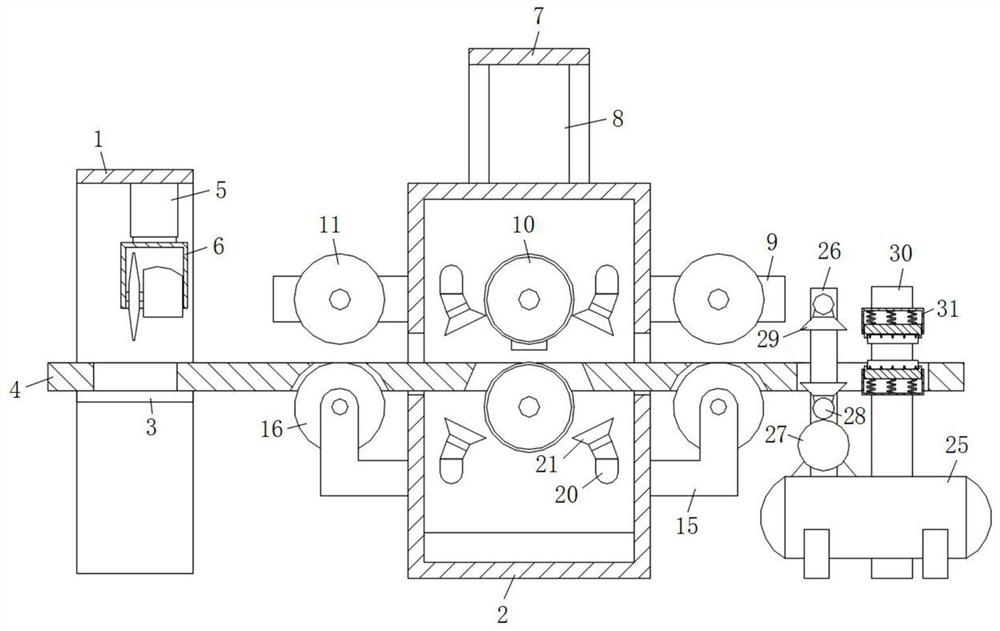
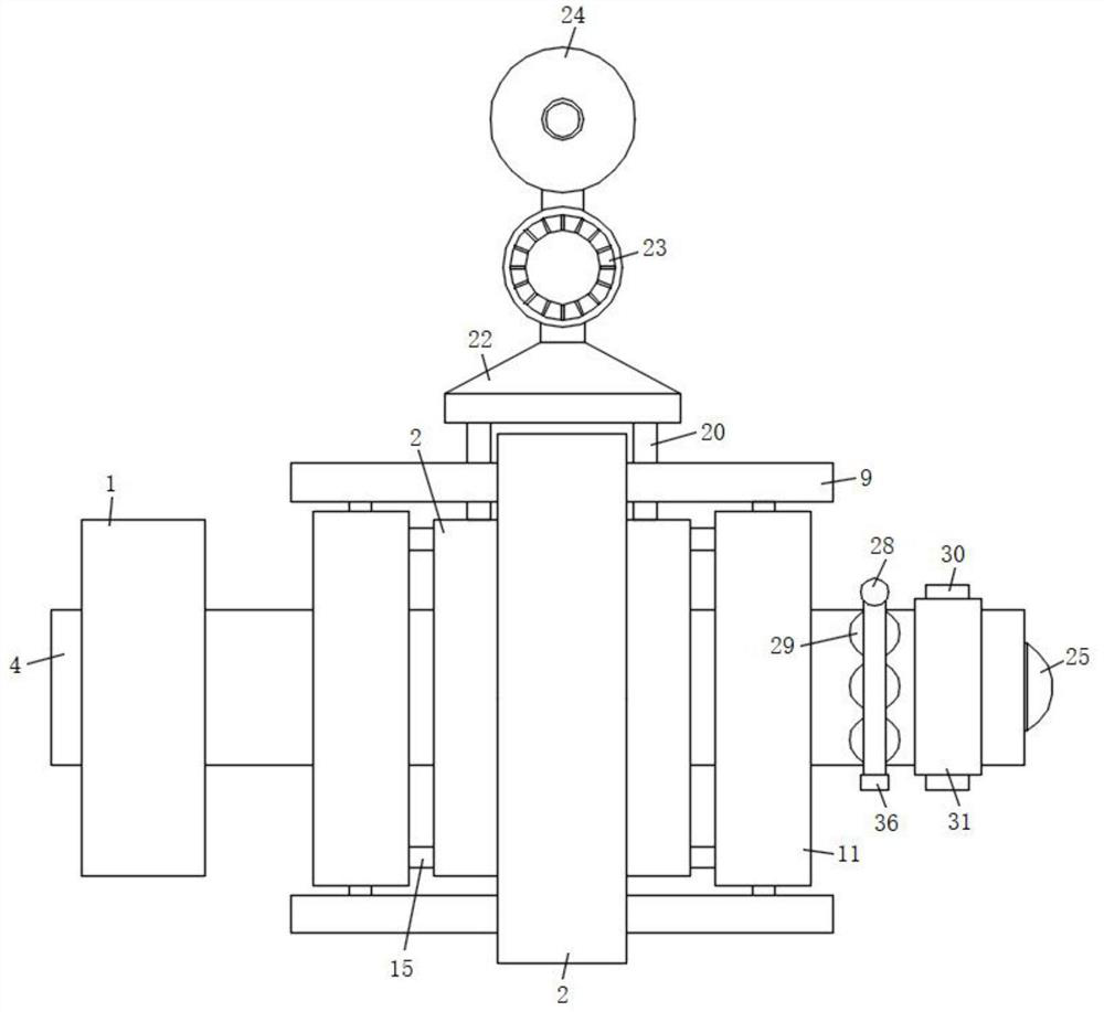
[0031] refer to Figure 1-4 , a wood surface processing device, including a cutting frame 1 and a grinding chamber 2, the middle part of the inner wall of the front and rear ends of the cutting frame 1 is also fixedly connected with a support plate 3, and both sides of the grinding chamber 2 are provided with rectangular holes, and the rectangular holes A working plate 4 is also fixedly connected between the inner bottom surface and the top surface of the support plate 3, and the inner top surface of the cutting frame 1 is also fixedly connected with a cylinder one 5 by screws, and the output end of the cylinder one 5 is fixedly connected with a cutting machine 6 by screws, and the grinding The top surface outside the room 2 is also fixedly connected with a mounting frame 7, the front and rear sides of the bottom of the mounting frame 7 are fixedly connected with a cylinder 2 8 by screws, and the output ends of the cylinder 2 8 are all connected with a mounting strip 9 by screw...

Embodiment 2

[0034] Such as figure 1 and 2 As shown, this embodiment is basically the same as Embodiment 1. Preferably, there are four dust suction pipes 20 distributed on both sides of the grinding roller 10, and the dust collecting funnels 21 are all directed from the outside of the grinding room 2 to the center of the grinding room 2. Tilt setting.

[0035] In this embodiment, dust collecting funnels 21 are arranged on both sides of the grinding roller 10, so that the dust after the plank is polished can be absorbed in time, and the working environment for plank processing is well guaranteed.

Embodiment 3

[0037] Such as figure 1 and 2 As shown, this embodiment is basically the same as Embodiment 1. Preferably, the upper part of the front and rear end side walls of the grinding chamber 2 is provided with a strip groove, and the rotating shaft of the grinding roller 10 is slidably connected in the strip groove, and the two sides of the working plate 4 The sides extend to the positions outside the cutting frame 1 and the grinding chamber 2 respectively.

[0038] In the present embodiment, the upper part of the front and rear end side walls of the grinding chamber 2 is provided with a bar-shaped groove, and the rotating shaft of the grinding roller 10 is slidably connected in the bar-shaped groove, thereby facilitating the adjustment of the position of the grinding roller 10.


PUM


Abstract

The invention discloses a wood board surface machining treatment device which comprises a cutting frame and a polishing chamber; a supporting plate is further fixedly connected to the middle of the inner wall of the front end and the middle of the inner wall of the rear end of the cutting frame, rectangular holes are formed in the two sides of a polishing chamber in a penetrating mode, and a working plate is further fixedly connected between the bottom faces of the interiors of the rectangular holes and the top face of the supporting plate; a first air cylinder is fixedly connected to the inner top face of the cutting frame through screws, a cutting machine is fixedly connected to the output end of the first air cylinder through screws, a mounting frame is fixedly connected to the outer top face of the polishing chamber, second air cylinders are fixedly connected to the front side and the rear side of the bottom face of the mounting frame through screws, and mounting strips are fixedlyconnected to the output ends of the second air cylinders through screws; and polishing rollers are rotatably connected to the middles of the two mounting strips and the lower sides of the inner wallsof the front end and the rear end of the polishing chamber correspondingly, and first pushing rollers are further rotatably connected to the two sides of the two mounting strips. The wood board surface machining treatment device is reasonable in design and stable, continuous machining operation of wood boards is easy and convenient, double-face polishing and waxing operation of the wood boards can be achieved at the same time, and the working efficiency of wood board machining is greatly improved.

Description

technical field [0001] The invention relates to the technical field of wood board production equipment, in particular to a wood board surface processing device. Background technique [0002] A wood board is a wood board made of complete wood. During the production process of a wood board, it usually needs to go through processes such as rough grinding, waxing and polishing, which requires the use of wood board processing equipment. [0003] After retrieval, the patent application number 202010127278.0 discloses a wood surface processing device, including a frame, a processing mechanism, and a loading and feeding mechanism; the processing mechanism is set on the frame and processes the wooden boards fed into it; The mechanism is located on one side of the frame, and is used to load the planks and drive the planks to turn over and send the planks to the processing mechanism. [0004] The above-mentioned device realizes double-sided processing of wood boards by turning over wh...

Claims


Application Information

Patent Timeline
Patent Type & Authority Applications(China)
IPC IPC(8): B24B7/17B24B7/06B24B7/28B24B27/00B24B47/22B24B55/06B24B55/12B27C5/02B27K3/12
CPCB24B7/06B24B7/17B24B7/28B24B27/0069B24B27/0076B24B47/22B24B55/06B24B55/12B27C5/02B27K3/12
Inventor 陈小根
Owner 怀宁县三兴木业有限公司
Why Eureka
Try Eureka