Semi-mechanical machining forming equipment for automobile axle tube

A technology for processing and forming automobile axles, which is used in metal processing equipment, grinding/polishing equipment, manufacturing tools, etc., and can solve the problems of pipe mouth grinding, rough pipe mouth, and unfavorable axle pipe welding and forming.

Inactive Publication Date: 2021-06-04
XIJING UNIV
View PDF3 Cites 0 Cited by
  • Summary
  • Abstract
  • Description
  • Claims
  • Application Information

AI Technical Summary

Problems solved by technology

[0005] However, the above-mentioned solution cannot polish the nozzle of the axle tube. If the grinding is not thorough, it will easily cause the nozzle to be rough, which is not conducive to the welding and forming between the axle tubes. Therefore, the present invention proposes semi-mechanized processing and forming equipment for automobile axle tubes to solve the existing problems in technology

Method used


Image

  • Semi-mechanical machining forming equipment for automobile axle tube
  • Semi-mechanical machining forming equipment for automobile axle tube

Examples


Embodiment 1

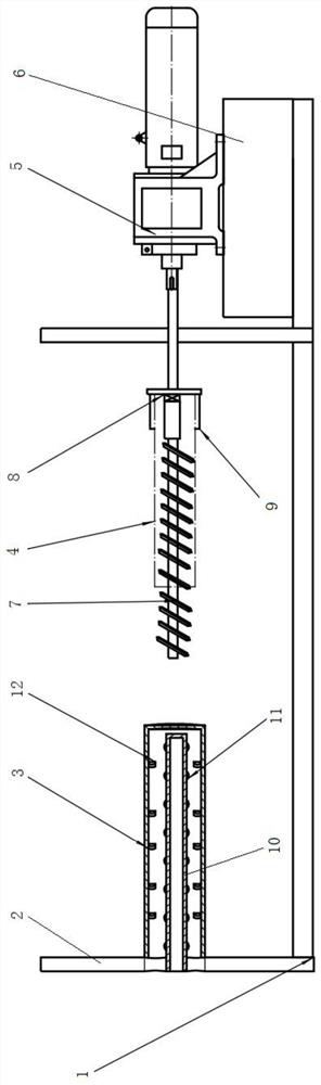
[0020] according to figure 1 As shown, this embodiment proposes semi-mechanized processing and forming equipment for automobile shaft tubes, including a base 1, and load-bearing plates 2 are installed on the left and right sides above the base 1, and the load-bearing plates 2 on the left and right sides are respectively installed There is a hollow grinding channel 3 and a clamping and progressive mechanism. The inner side of the hollow grinding channel 3 is equipped with grinding components, and multiple groups of grinding components are equidistantly arranged. The multiple groups of grinding components are distributed in the hollow grinding The inner side of the channel 3, the inner side of the hollow grinding channel 3 is provided with an internal grinding mechanism, the clamping and advancing mechanism is used for installing the shaft tube 4, and the movement stroke of the clamping and advancing mechanism is greater than the length of the hollow grinding channel 3.

[0021]...

Embodiment 2

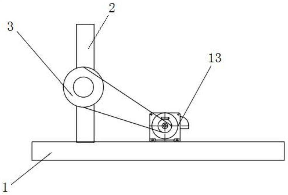
[0028] according to figure 1 , figure 2 As shown, this embodiment proposes semi-mechanized processing and forming equipment for automobile shaft tubes, including a base 1, and load-bearing plates 2 are installed on the left and right sides above the base 1, and the load-bearing plates 2 on the left and right sides are respectively installed There is a hollow grinding channel 3 and a clamping and progressive mechanism. The inner side of the hollow grinding channel 3 is equipped with grinding components, and multiple groups of grinding components are equidistantly arranged. The multiple groups of grinding components are distributed in the hollow grinding The inner side of the channel 3, the inner side of the hollow grinding channel 3 is provided with an internal grinding mechanism, the clamping and advancing mechanism is used for installing the shaft tube 4, and the movement stroke of the clamping and advancing mechanism is greater than the length of the hollow grinding channel...


PUM


Abstract

The invention discloses semi-mechanical machining forming equipment for an automobile axle tube. The semi-mechanical machining forming equipment comprises a base, bearing plates are installed on the left side and the right side of the upper portion of the base, a hollow grinding channel and a clamping progressive mechanism are installed on the bearing plates on the left side and the right side correspondingly, grinding assemblies are installed on the inner side of the hollow grinding channel, the multiple sets of grinding assemblies are arranged at equal intervals, the multiple sets of grinding assemblies are sequentially distributed on the inner side of the hollow grinding channel from left to right, an inner grinding mechanism is arranged on the inner side of the hollow grinding channel, the clamping progressive mechanism is used for installing the axle tube, and the movement stroke of the clamping progressive mechanism is larger than the length of the hollow grinding channel. According to the semi-mechanical machining forming equipment for the automobile axle tube, through cooperation of the hollow grinding channel and a grinding column, double-face grinding of the axle tube is achieved, the inner tube wall and the outer tube wall of the axle tube are formed and machined in one-time grinding process, then through arranged bristles, grinding and polishing of an axle tube opening are achieved, and practicability is high.

Description

technical field [0001] The invention relates to the technical field of mechanical automation equipment, in particular to semi-mechanized processing and forming equipment for automobile shaft tubes. Background technique [0002] The shaft tube is a tubular structure part. The shaft tube is used as a tubular connector. Its surface and end are required to be smooth to avoid scratches during transportation or handling. The end of the shaft tube needs to be repaired as needed. Chamfer to facilitate the connection of the shaft tube. In different applications, the length of the shaft tube required is different. During the production process, the semi-finished shaft tubes cut to a certain length are stacked and placed. Before reaching the next process, they need to be stacked. The shaft tubes are separated one by one for subsequent processing. [0003] The current shaft tube is a component with a tubular structure. However, because there may be burrs on the surface of the shaft tub...

Claims


Application Information

Patent Timeline
Patent Type & Authority Applications(China)
IPC IPC(8): B24B9/00B24B41/04B24B41/06B24B47/12B24B41/02
CPCB24B9/002B24B9/007B24B41/02B24B41/04B24B41/062B24B47/12
Inventor 赵金国刘守法
Owner XIJING UNIV
Why Eureka
Try Eureka