Medical scalpel cutting edge grinding device

A grinding and cutting edge technology, applied in the field of medical scalpel edge grinding devices, can solve problems such as low efficiency and difficulty in ensuring product quality stability, and achieve the effects of reducing energy consumption, product quality stability, and improving production efficiency

Pending Publication Date: 2021-03-16
QINGDAO TECHNOLOGICAL UNIVERSITY
View PDF10 Cites 0 Cited by
  • Summary
  • Abstract
  • Description
  • Claims
  • Application Information

AI Technical Summary

Problems solved by technology

[0004] According to the understanding, the inventor found that the current scalpel can only be sharpened on one side, and the grinding and sharpening of stamping blanks are all done manually. Such a process will cause low efficiency, and it is difficult to guarantee the product by manual operation. quality stability

Method used


Image

  • Medical scalpel cutting edge grinding device
  • Medical scalpel cutting edge grinding device
  • Medical scalpel cutting edge grinding device

Examples


Embodiment 1

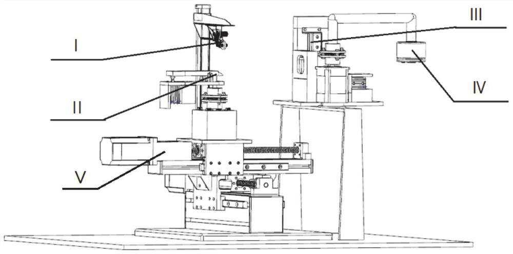
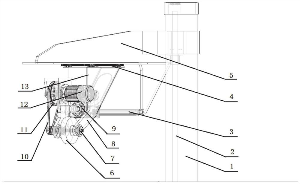
[0037] In a typical embodiment of the present invention, such as Figure 1-Figure 5 As shown, a medical scalpel edge grinding device is proposed, including grinding mechanism I, clamping mechanism II, loading mechanism III, and unloading mechanism IV; wherein, the bottom of the clamping mechanism is set on the two-dimensional mobile platform V, The grinding mechanism I is correspondingly arranged above the clamping mechanism II, and the loading mechanism III and the unloading mechanism IV are arranged at the relative positions of the clamping mechanism II, and the loading mechanism, the unloading mechanism and the clamping mechanism are separated by a certain distance.

[0038] The bottom of the loading mechanism and the unloading mechanism can be arranged on the bracket, so that the height of the loading mechanism, the unloading mechanism and the clamping mechanism correspond; the bracket and the bottom of the two-dimensional mobile platform can be fixed on the workbench.

[...

Embodiment 2

[0064] Propose a kind of working method of medical scalpel edge grinding device in the present embodiment, comprise the following steps:

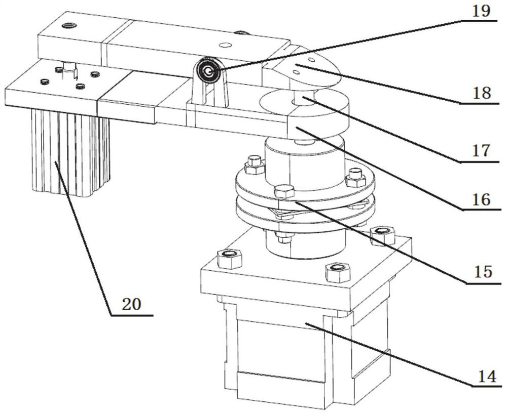
[0065] Step 1: put the blade to be ground into the tool holder 23, and press it under the action of the blade pressing plate 25, and push the blade out from the tool holder 23 under the combined action of the pusher cylinder 22 and the pusher plate 21;

[0066] Step 2: The two-dimensional mobile platform carries the duckbill-shaped clamping end 18 and moves to the knife-out position, when the right end of the duckbill-shaped clamping end 18 moves downward with the help of the clamp booster cylinder 20 to combine with the clamp base and When locked, the clamping of the blade is completed. At this time, the gas spring 17 located under the clamping end is compressed, and the elastic force of the gas spring 17 is given by the clamp power cylinder 20 through the upper end of the clamp. The clamp power cylinder is locked and clamped. The end clam...


PUM


Abstract

The invention discloses a medical scalpel cutting edge grinding device. The device comprises a grinding mechanism, a clamping mechanism, a feeding mechanism and an unloading mechanism, wherein the bottom of the clamping mechanism is arranged on a two-dimensional moving platform, the grinding mechanism is correspondingly arranged above the clamping mechanism, and the feeding mechanism and the unloading mechanism are arranged at positions opposite the clamping mechanism. According to the device, the feeding mechanism pushes a blade to the clamping mechanism to be clamped, the grinding mechanismmoves to a to-be-ground position to grind the blade, then the clamping mechanism loosens the blade, and the blade is unloaded by the unloading mechanism, so that the cutting edge of a medical scalpelis automatically ground.

Description

technical field [0001] The invention belongs to the technical field of scalpel grinding, and in particular relates to a medical scalpel edge grinding device. Background technique [0002] The statements herein merely provide background information related to the present invention and do not necessarily constitute prior art. [0003] Scalpel is a relatively common tool in medical treatment, widely used in various operations, and is one of the most common medical consumables. The production process of the scalpel is roughly divided into important steps such as stamping, grinding, and polishing. [0004] According to the knowledge, the inventor found that the current scalpel can only be sharpened on one side, and the grinding and sharpening of stamping blanks are all done manually. Such a process will cause low efficiency, and it is difficult to guarantee the product by manual operation. quality stability. Contents of the invention [0005] Aiming at the deficiencies in th...

Claims


Application Information

Patent Timeline
Patent Type & Authority Applications(China)
IPC IPC(8): B24B3/60B24B41/00B24B41/06B24B41/02B24B47/06B24B47/12B24B55/00
CPCB24B3/605B24B41/005B24B41/06B24B41/02B24B47/06B24B47/12B24B55/00
Inventor 王德祥张宇江京亮刘国梁
Owner QINGDAO TECHNOLOGICAL UNIVERSITY
Why Eureka
Try Eureka