Burner for gas stove

A technology of gas stoves and burners, applied in the direction of gas fuel burners, burners, combustion methods, etc., can solve the problems of small heat load, high cost, incomplete gas, etc., and achieve reduced overall height, compact structure, and stable flames Effect

Active Publication Date: 2020-04-07
NINGBO FOTILE KITCHEN WARE CO LTD
View PDF9 Cites 2 Cited by
  • Summary
  • Abstract
  • Description
  • Claims
  • Application Information

AI Technical Summary

Problems solved by technology

Among them, although the way of side air intake has the advantages of small air intake resistance and large air intake volume, there are still problems in the existing side air intake burners such as: due to the ejection effect of the combustion hot air flow, the internal and external fire The cover will entrain secondary air through the side air inlet of the air mixing chamber. The heat load of the inner ring is small, and the primary air coefficient is higher than that of the outer ring. However, the secondary air entrainment is insufficient. In order to distribute the secondary air reasonably and achieve full combustion of the inner and outer rings at the same time, and if the secondary air supplementary channel is too large, the amount of secondary air will be entrained and the smoke will be taken away. The increase of heat leads to low thermal efficiency; the secondary air supply channel is too small, and the insufficient secondary air supply will inevitably lead to incomplete combustion, and the flue gas emission exceeds the standard. In the case of insufficient secondary air, the primary air supply must be increased to reduce The demand for secondary air, so the core of improving the energy efficiency of atmospheric burners is to increase the primary air ratio and enhance the ejection capacity
For this reason, the Chinese invention patent of the pa

Method used


Image

  • Burner for gas stove
  • Burner for gas stove
  • Burner for gas stove

Examples


Embodiment Construction

[0031] The present invention will be further described in detail below in conjunction with the accompanying drawings and embodiments.

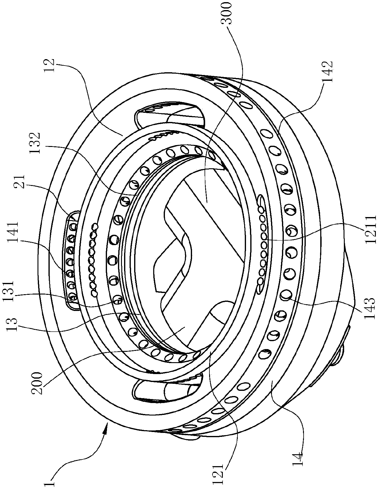
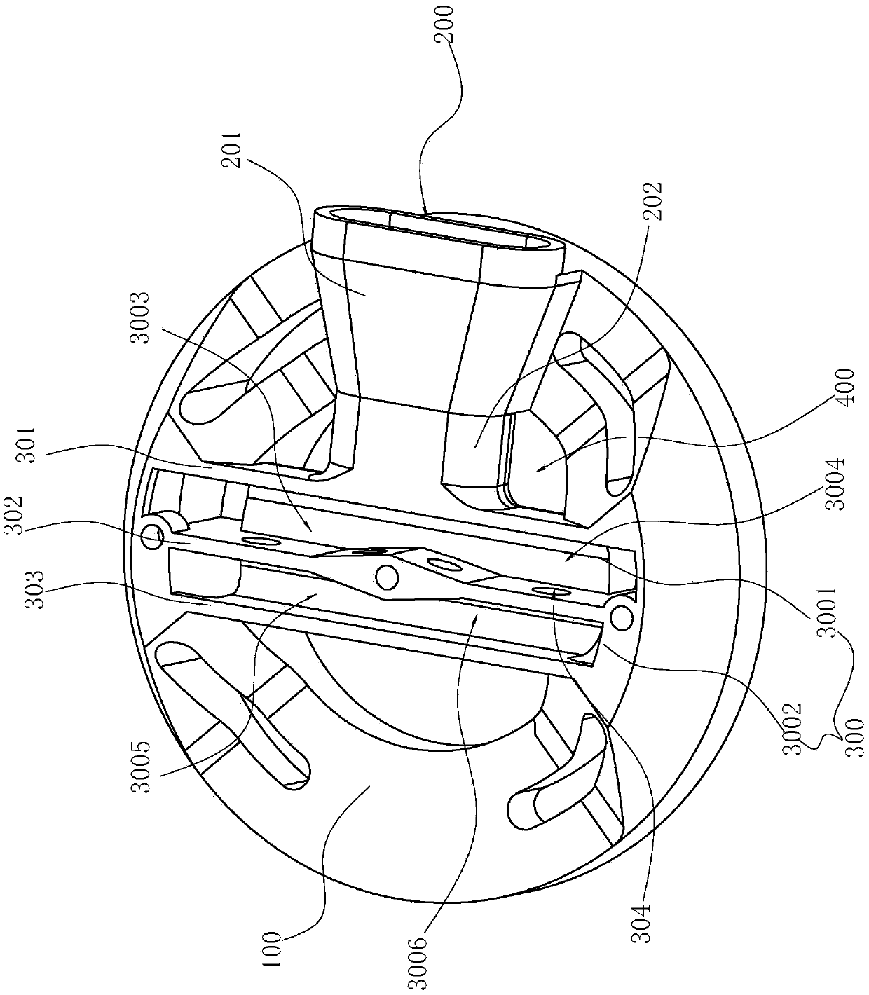
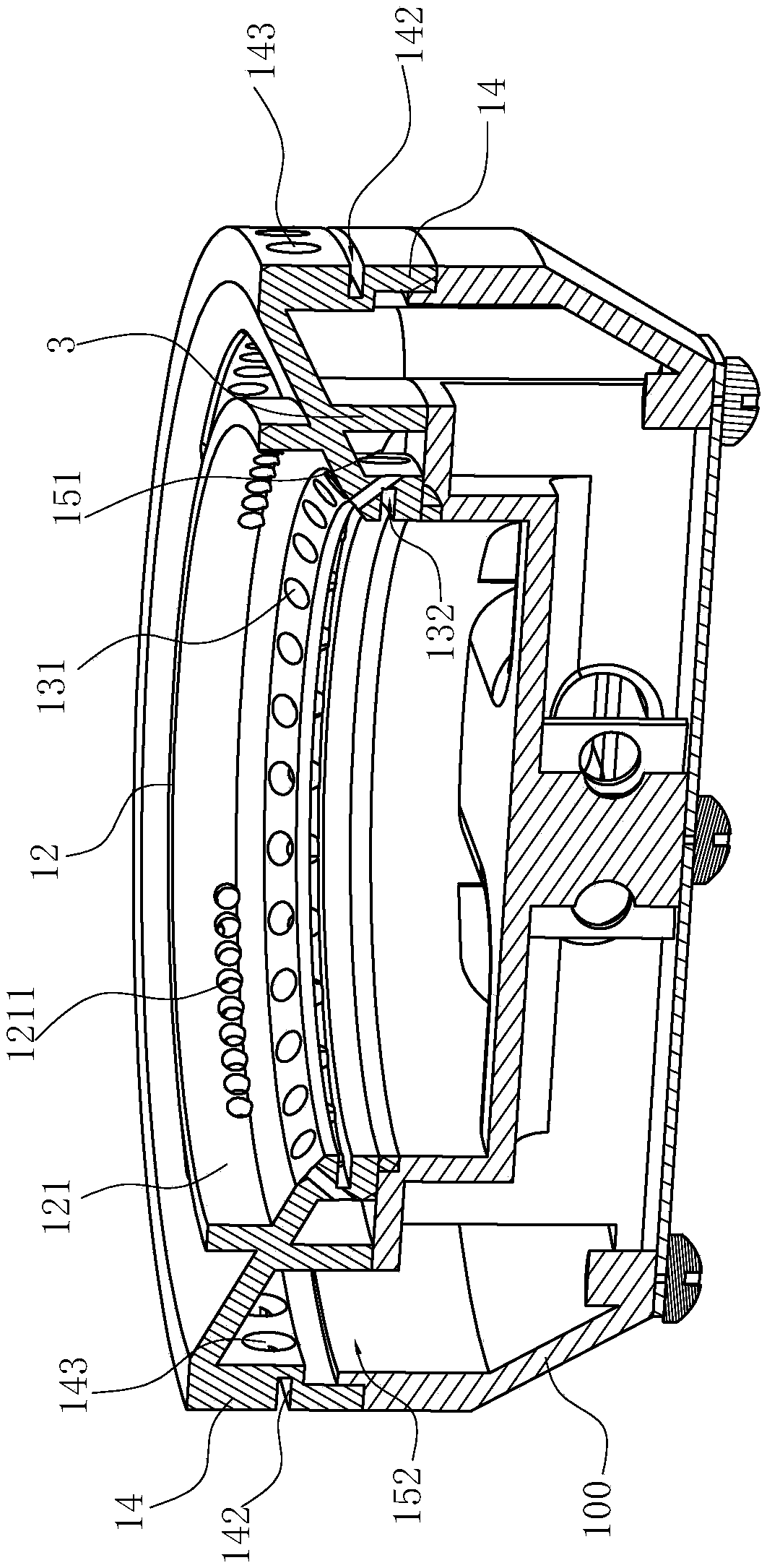
[0032] Such as Figure 1~6As shown, the burner used in the gas stove includes a base 100, the base 100 has an injection tube 200 arranged at the bottom of the base 100, arranged on the base 100, and between the base 100 The fire cover 1 that forms a relatively independent gas mixing chamber 15, and is arranged at the bottom of the base 100 and runs through the central position of the base 100 longitudinally, including a gas channel that communicates with the gas mixing chamber 15 and the injection pipe 200 300, in order to form a central fire and a peripheral fire in the fire cover 1 of the burner, the air mixing chamber 15 includes a first air mixing chamber 151 located on the inside and a second air mixing chamber 152 located on the outside, and the gas channel 300 includes The first partition 301, the second partition 302 and the third par...


PUM


Abstract

The invention relates to a burner for a gas stove. The burner is characterized by comprising a pedestal. The pedestal is provided with an injection pipe, a burner cap and a gas channel, wherein the injection pipe is arranged at the bottom of the pedestal; the burner cap is arranged on the pedestal and forms an independent gas mixing chamber with the pedestal; and the gas channel is arranged at thebottom of the pedestal and penetrates the center position of the pedestal longitudinally. The gas channel comprises a runner communicating to the gas mixing chamber and the injection pipe. Compared with the prior art, the burner has the advantages that the conventional gas mixing chamber, injection pipe and pedestal are integrated, and meanwhile, the conventional inner and outer ring burner capsare integrated, so that the whole burner is minimized; in addition, the runner of the gas channel can replace an expanded segment of an existing injection pipe, and meanwhile, the runner is designed to prolong the injection pipe, so that the injection ability can be also enhanced while the integral height of the burner is reduced so as to generate a good gas and primary air mixing effect. Therefore, the integral burner is in a good burning working condition.

Description

technical field [0001] The invention relates to the field of household gas stoves, in particular to a burner for a gas stove. Background technique [0002] The primary air coefficient of existing atmospheric stove burners is generally 0.4-0.7, and the premixed air cannot reach the air volume required for complete combustion. In addition to various factors, a certain amount of secondary air is required, and in order to reduce CO emission, secondary air supplement should be as sufficient as possible. At present, there are various ways of replenishing air for stove burners. Generally, there are side air intake and bottom air intake. The air inlet is supplemented with secondary air, and the way of lower air intake is to open the lower air inlet at the base base, and the air under the cooker is supplemented with secondary air through the lower air inlet. Among them, although the way of side air intake has the advantages of small air intake resistance and large air intake volume...

Claims


Application Information

Patent Timeline
IPC IPC(8): F23D14/06F23D14/48F23D14/64F23D14/46
CPCF23D14/06F23D14/46F23D14/48F23D14/64
Inventor 程永超郑军妹
Owner NINGBO FOTILE KITCHEN WARE CO LTD
Why Eureka
Try Eureka