Main shaft of photovoltaic tracking support

A main shaft and photovoltaic technology, applied in the direction of control using feedback, can solve the problems of increasing eccentric force, increasing distance, increasing cost, etc., and achieve the effect of good practical application value.

Inactive Publication Date: 2020-04-07
XIAMEN ANTAI NEW ENERGY TECH
View PDF0 Cites 3 Cited by
  • Summary
  • Abstract
  • Description
  • Claims
  • Application Information

AI Technical Summary

Problems solved by technology

[0003] Since the main shaft of the photovoltaic tracking bracket needs to achieve a certain bending strength, the main shaft commonly used in the industry is usually a square tube or a round tube. In order to achieve the corresponding strength and rigidity, it is usually selected to enlarge its outer diameter specification, and its weight is relatively heavy. large, the cost increases
And as the outer diameter becomes larger, the distance between the tracking bracket panel assembly and the bearing rotation center gradually becomes farther, and the eccentric force becomes larger

Method used


Image

  • Main shaft of photovoltaic tracking support
  • Main shaft of photovoltaic tracking support
  • Main shaft of photovoltaic tracking support

Examples


Embodiment 1

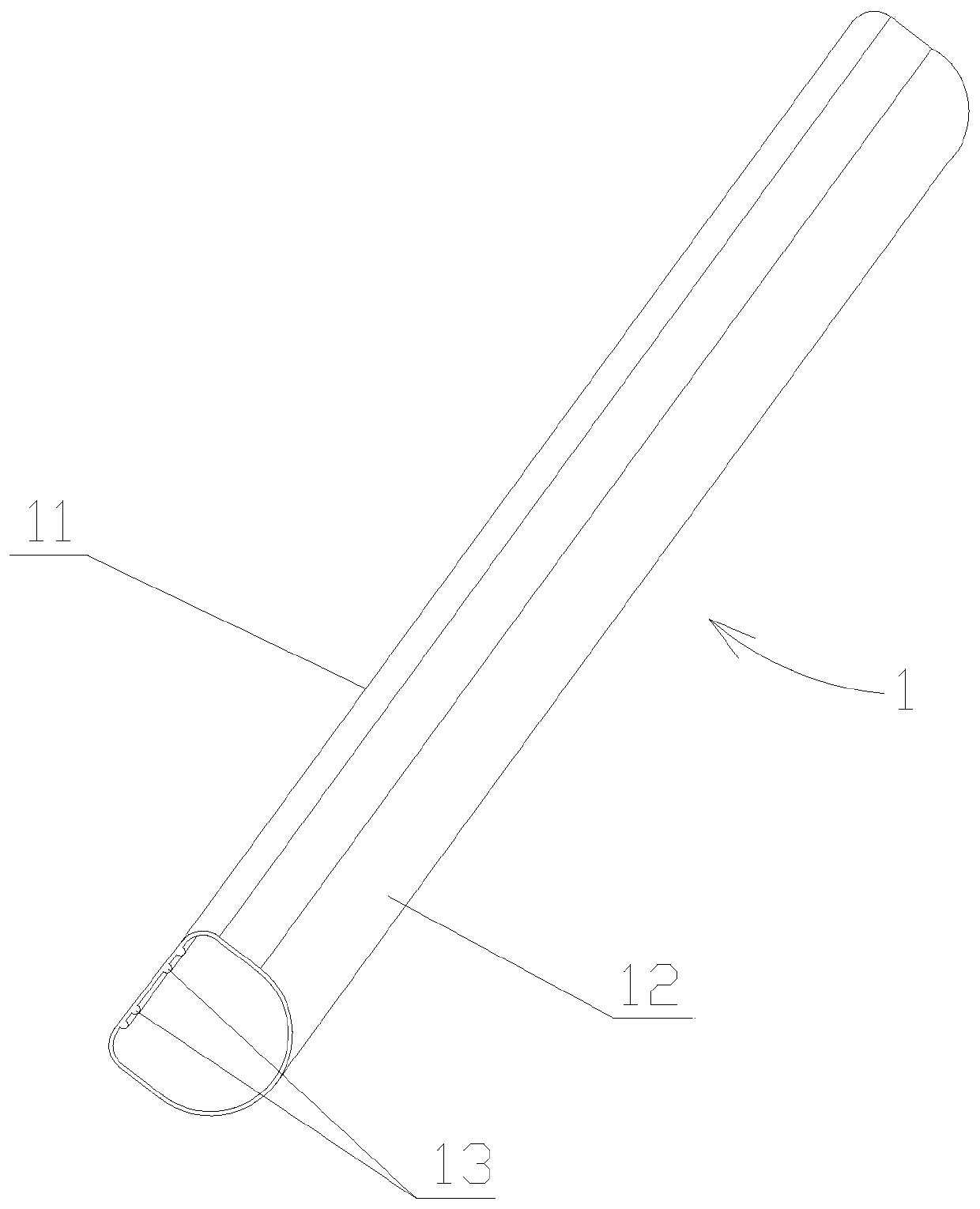
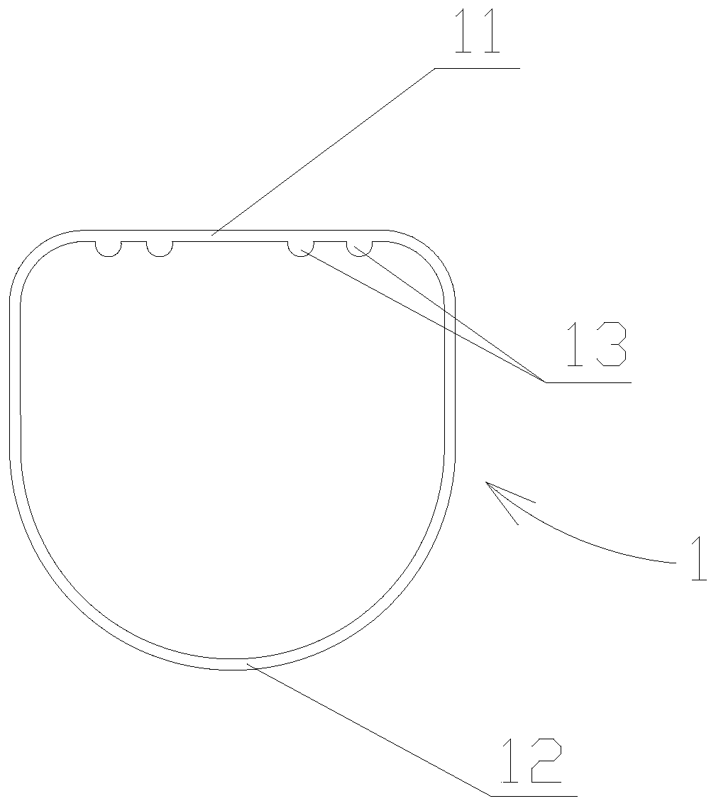
[0029] figure 1 and figure 2 Schematically shows the main axis of the photovoltaic tracking bracket according to an embodiment of the present invention. As shown, the main shaft 1 is made of a tube with a closed section.

[0030] The installation surface 11 on one side of the main shaft 1 for installing purlins is a plane.

[0031] Both sides of the main shaft 1 are perpendicular to the mounting surface 11 .

[0032] The side of the main shaft 1 opposite to the mounting surface 11 is an arc surface 12 .

[0033] Spindle 1 has the same width on both sides.

[0034] The mounting surface 11 and the arcuate surface 12 are respectively disposed on the plane member 21 and the arcuate member 22 .

[0035] The inner wall of the installation surface 11 is provided with a strengthening device, and the reinforcement device is used to strengthen the strength of the installation surface 11 . Since the installation surface 11 needs to be connected with purlins, holes are usually open...

Embodiment 2

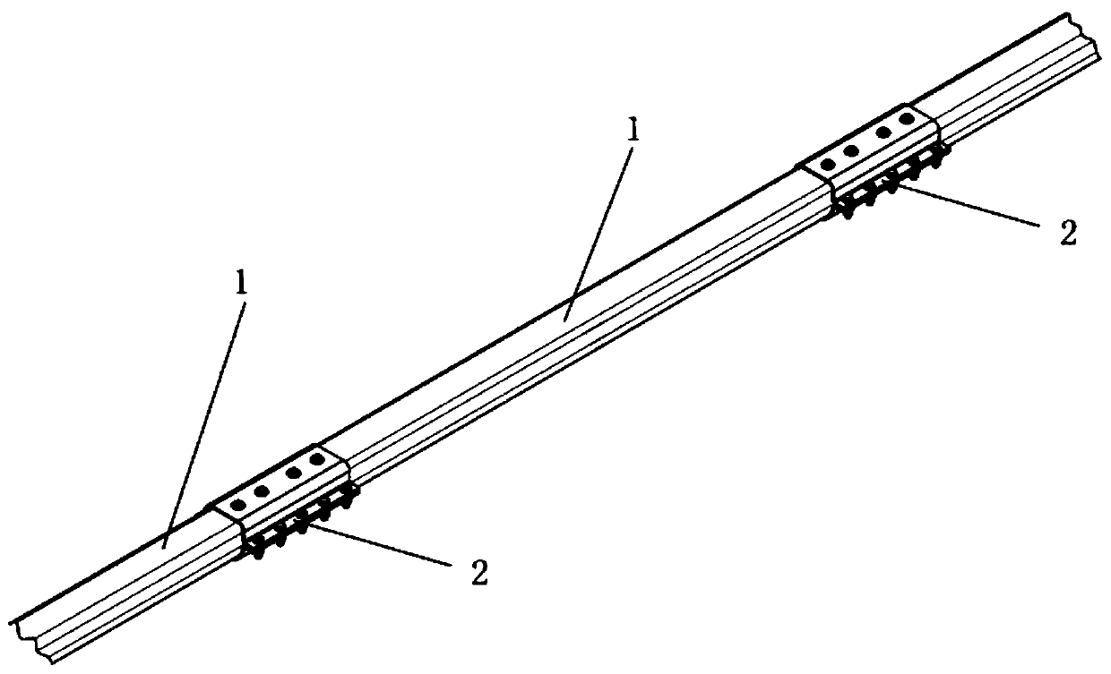
[0044] Figure 3 to Figure 5 It schematically shows the main axis of the photovoltaic tracking bracket according to another embodiment of the present invention. As shown in the figure, the difference from Embodiment 1 is that a plurality of main shafts are connected to one coaxial center through a main shaft connecting piece.

[0045] The main shaft connecting piece 2 is sleeved and fixed at the joint with the main shaft 1 .

[0046] The main shaft connecting piece 2 is composed of a plurality of planar pieces 21 and curved surface pieces 22 .

[0047] The mounting surface 11 and the circular arc surface 12 are respectively disposed in the plane member 21 and the arc surface member 22 .

[0048] The plane piece 21 and the arc surface piece 22 are fixedly connected and enclosed into a closed tubular shape.

[0049] The span of a single row of photovoltaic tracking brackets is usually long, and the entire main shaft is mostly formed by multi-segment locking. The spindle is f...

Embodiment 3

[0054] Figure 6It schematically shows the main axis of the photovoltaic tracking bracket according to another embodiment of the present invention. As shown in the figure, the difference from Embodiment 1 is that the reinforcing means is provided with several grooves 14 on the installation surface 11 .

[0055] The groove 14 is recessed into the main shaft 1 and its axial direction coincides with the axial direction of the main shaft 1 . The groove 14 can not only strengthen the strength of the installation surface 11 , but also increase the elasticity of the installation surface 11 , thereby buffering the instantaneous impact force of the purlin on the main shaft 1 .


PUM


Abstract

The invention discloses a main shaft of a photovoltaic tracking support, which is made of a pipe fitting with a closed section, a mounting surface of one side of the main shaft for mounting a purlineis a plane, two sides of the main shaft are vertical to the mounting surface, one side of the main shaft opposite to the mounting surface is an arc surface, and two sides of the main shaft have the same width. Due to the special shape of the main shaft of the photovoltaic tracking support adopting the technical scheme, when the main shaft is applied to the photovoltaic tracking support, the crosssection of the main shaft resists moment, compared with square and round main shafts in the prior art, under the condition that the same thickness is guaranteed, the resistance moment is greatly improved, and the main shaft has good practical application value. The resistance moment of the cross section of the main shaft is improved, the weight is lighter, the cost of the main shaft is saved, andthe eccentric force of the panel assembly is reduced. After the main shaft is applied to the photovoltaic tracking bracket, besides the technical effects, the stress of the photovoltaic tracking bracket is more uniform, and the installation is more convenient and faster.

Description

technical field [0001] The invention relates to solar photovoltaic equipment, in particular to a main shaft of a photovoltaic tracking bracket. Background technique [0002] In the prior art, photovoltaic power generation has become a trend and is widely used in various places. Photovoltaic power generation is based on the principle of photovoltaic effect to directly convert sunlight energy into electrical energy. Regardless of whether it is used independently or connected to the grid for power generation, the photovoltaic power generation system is mainly composed of three parts: purlins, controllers and inverters. In order to ensure that the purlins maintain high power generation efficiency, a photovoltaic tracking bracket was developed. The purlins are installed on the main shaft. The purlins are driven to rotate as the sun moves. [0003] Since the main shaft of the photovoltaic tracking bracket needs to achieve a certain bending strength, the main shaft commonly used i...

Claims


Application Information

Patent Timeline
Patent Type & Authority Applications(China)
IPC IPC(8): G05D3/12
CPCG05D3/12
Inventor 黄丽琴毛谦伟
Owner XIAMEN ANTAI NEW ENERGY TECH
Why Eureka
Try Eureka