Paint spraying device capable of automatically identifying width of insulator

An automatic identification, insulator technology, applied in the direction of spraying devices, etc., can solve the problems of operator fatigue and inability to guarantee spraying efficiency.

Inactive Publication Date: 2020-04-10
SHENGZHOU RUNYA ELECTRONICS TECH CO LTD
View PDF3 Cites 6 Cited by
  • Summary
  • Abstract
  • Description
  • Claims
  • Application Information

AI Technical Summary

Problems solved by technology

Generally, after the custom-made insulator is cut, the width will change, so that the parameters of the painting device must be reset every time the paint is sprayed, whi

Method used


Image

  • Paint spraying device capable of automatically identifying width of insulator
  • Paint spraying device capable of automatically identifying width of insulator
  • Paint spraying device capable of automatically identifying width of insulator

Examples


Embodiment Construction

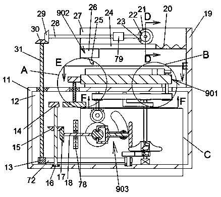
[0018] Combine below Figure 1-8 The present invention is described in detail, and for convenience of description, the orientations mentioned below are now stipulated as follows: figure 1 The up, down, left, right, front and back directions of the projection relationship itself are the same.

[0019] refer to Figure 1-8 According to an embodiment of the present invention, a paint spraying device that can automatically identify the width of an insulator includes a housing 11, and the upper end of the housing 11 is provided with a traversing assembly 901, and the traversing assembly 901 includes a The fixed support plate 36 on the upper end of the body 11, the support slider 35 that is located at the upper end of the fixed support plate 36 and can slide back and forth, and the upper end of the support slider 35 can place an insulator to be painted. Sliding back and forth to realize the lateral movement function, the upper end surface of the housing 11 is fixed with a support ...


PUM


Abstract

The invention discloses a paint spraying device capable of automatically identifying the width of an insulator. The paint spraying device comprises a shell, wherein a transverse moving assembly is arranged at the upper end of the shell and comprises a fixed supporting plate fixedly arranged at the upper end of the shell. According to the paint spraying device, a fixed rack and a fifth gear are adopted, when the insulator to be sprayed is placed at the upper end of a supporting sliding block, the fixed rack can move forwards under the rotation of the fifth gear and cooperates with a limiting baffle to clamp the insulator to be sprayed, so that the insulator is guaranteed not to slide during paint spraying; a radian friction wheel and a friction transmission wheel are adopted, when a seventhgear rotates, the friction transmission wheel and the radian friction wheel are driven by a connecting rod, a sliding block and a second transmission shaft to be in friction fit connection with eachother at the position with larger radian, and the rotating angle of the friction transmission wheel can be adjusted along with the widths of different insulators, so that the rotating speed of a firstgear is changed, the moving speed of the supporting sliding block is changed, and paint spraying of the insulators with different widths is realized.

Description


Claims


Application Information

Patent Timeline
Owner SHENGZHOU RUNYA ELECTRONICS TECH CO LTD
Why Eureka
Try Eureka