
Tire mold side plate and tire mold

A tire mold and side plate technology, which is applied in the field of tire mold side plates and tire molds, can solve the problems of reduced mold precision, easy damage to movable type blocks or side plates, etc., and achieves the effect of avoiding safety accidents, ensuring appearance, and avoiding gaps.

Active Publication Date: 2020-04-10
HIMILE MECHANICAL SCI & TECH (SHANDONG) CO LTD
View PDF6 Cites 0 Cited by
  • Summary
  • Abstract
  • Description
  • Claims
  • Application Information

AI Technical Summary

Problems solved by technology

[0004] The purpose of the present invention is to provide a tire mold side plate, so as to alleviate the technical problem that the dismounting method of the movable type block in the prior art is easy to damage the mating surface of the movable type block or the groove on the side plate, resulting in a decrease in mold precision

Method used


Image

  • Tire mold side plate and tire mold
  • Tire mold side plate and tire mold
  • Tire mold side plate and tire mold

Examples


Embodiment

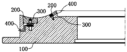
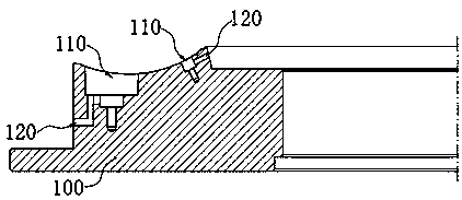
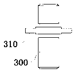
[0048] This embodiment provides a tire mold side plate, combined with figure 1 and figure 2 , the tire mold side plate includes a base 100, a movable type block 200, a connector 300 and a driving member; Between the movable type blocks 200 , the driving member is in transmission connection with the connecting member 300 and can drive the connecting member 300 to rotate, so that the movable type block 200 moves relative to the groove 110 to fit into the groove 110 or extend out of the groove 110 .

[0049]In the side plate of the tire mold provided in this embodiment, a connecting piece 300 is connected between the groove 110 and the movable type block 200, wherein the connecting piece 300 is in transmission connection with the driving piece, and the driving piece can drive the connecting piece 300 to rotate. During the rotation of 300, the movable type block 200 can move relative to the groove 110 to fit into the groove 110 or protrude from the groove 110; as can be seen fro...


PUM


Abstract

The invention provides a tire mold side plate and a tire mold, and relates to the technical field of tire vulcanization mold manufacturing. The tire mold side plate comprises a base body, movable typeblocks, connecting pieces and driving pieces, wherein the base body is provided with grooves, the connecting pieces are connected between the grooves and the movable type blocks, and the driving pieces are in transmission connection with the connecting pieces and can drive the connecting pieces to rotate, so that the movable type blocks move relative to the grooves to be embedded into the groovesor extend out of the grooves. The tire mold comprises the tire mold side plate. The technical problem is solved that in the prior art, a detachment method of the movable type blocks is liable to cause damage to the matching surfaces of the movable type blocks or the grooves in the side plate, and consequently the precision of the mold is reduced.

Description

technical field [0001] The invention relates to the technical field of mold manufacturing for tire vulcanization, in particular to a tire mold side plate and a tire mold. Background technique [0002] In order to meet market demand and achieve product traceability, it is necessary to frequently replace tire sidewall content, such as codes, fonts, etc., which are generally made in the form of movable type blocks. [0003] In the prior art, the fit between the movable type block and the side plate generally adopts an interference fit and is fixed with screws. In general, the conventional disassembly method is to use destructive knocking from the front or knocking from the back of the side plate after turning over the side plate. This disassembly method is very inconvenient, and it is easy to damage the mating surface of the movable type block or the groove on the side plate, thereby reducing the precision of the mold, resulting in difficulty in assembly or gaps after assembly...

Claims


Application Information

Patent Timeline
Patent Type & Authority Applications(China)
IPC IPC(8): B29D30/06
CPCB29D30/0606B29D2030/0607
Inventor 夏世涛张恭运孙日文王万里杜平王磊
Owner HIMILE MECHANICAL SCI & TECH (SHANDONG) CO LTD
Learn More