Non-bearing frame longitudinal beam

A non-load-bearing, longitudinal beam technology, applied in the direction of vehicle components, substructure, transportation and packaging, can solve the problems of increasing the mass and manufacturing cost of the vehicle, not considering the performance of the longitudinal beam, affecting the bending resistance, etc. Effects of light weight, enhanced bending stiffness, reduced manufacturing and production costs

Inactive Publication Date: 2020-04-10
NANJING UNIV OF SCI & TECH
View PDF6 Cites 0 Cited by
  • Summary
  • Abstract
  • Description
  • Claims
  • Application Information

AI Technical Summary

Problems solved by technology

[0004] Chinese invention patent application "a front longitudinal beam structure with continuously variable section and thickness for function customization" (application number: 201708511507 publication date: ) discloses a front longitudinal beam with continuously variable section and thickness for function customization Structure, the two adjacent functional areas realize continuous transition connection through the thickness transition area, reduce the number of parts, and improve the impact energy absorption capacity of the front longitudinal beam to a certain extent, but the structure of the front longitudinal beam above When it is long, it is prone to fatigue failure in the connection of different functional areas, which greatly affects its bending resistance under heavy load
[0005] In short, the problem existing in the existing technology is that the current improvement of the crashworthiness of the vehicle frame is only achieved by increasing the thickness or changing the cross-sectional shape of the longitudinal beam, which will significantly increase the quality of the vehicle and the manufacturing cost
It does not take into account the method of filling the structure inside the frame to improve the performance of the longitudinal beam

Method used


Image

  • Non-bearing frame longitudinal beam
  • Non-bearing frame longitudinal beam
  • Non-bearing frame longitudinal beam

Examples


Embodiment Construction

[0017] The present invention will be further described below in conjunction with specific embodiments to help those skilled in the art have a more complete, accurate and in-depth understanding of the inventive concept and technical solution of the present invention.

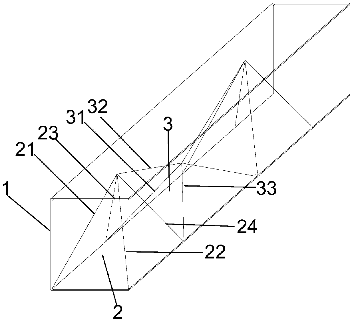
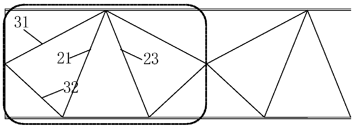
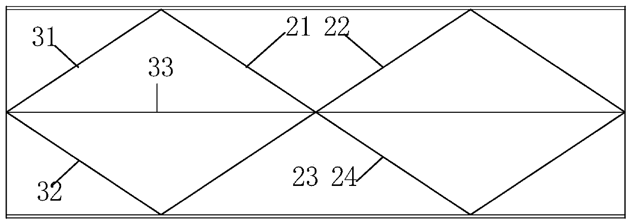
[0018] Such as figure 1 , 2 , 3, and 4, the non-load-bearing frame longitudinal beam of the present invention includes the 匚-shaped side member body 1, and also includes the 匚-shaped side member body 1 inside and along the axis of the 匚-shaped side member body 1, etc. At least two regular quadrangular pyramid frames 2 are arranged at intervals, two fixedly connected tetrahedral frames 3 are provided between two adjacent regular quadrangular pyramid frames 2, and the two ends of the two connected tetrahedral frames 3 are connected to the two The regular quadrangular pyramid frame 2 is fixedly connected.

[0019] Preferably, the regular quadrangular pyramid frame 2 and the tetrahedral frame 3 are integrally cast with th...


PUM


Abstract

The invention discloses a non-bearing frame longitudinal beam. The longitudinal beam comprises a C-shaped longitudinal beam body (1), and also comprises at least two right square pyramid frames (2) which are arranged on the inner side of the C-shaped longitudinal beam body (1) and are arranged along the axis of the C-shaped longitudinal beam body (1) at equal intervals, two fixedly connected tetrahedron frames (3) are arranged between every two adjacent right square pyramid frames (2), and the two ends of the two connected tetrahedron frames (3) are fixedly connected with the two right squarepyramid frames (2) respectively. The non-bearing frame longitudinal beam is good in collision resistance and light in weight.

Description

Technical field [0001] The invention relates to the field of structural optimization of automobile longitudinal beams, in particular to a non-load-bearing frame longitudinal beam with good crash resistance and light weight. Background technique [0002] Non-load-bearing body refers to the part that is combined by the two parts of the carriage and the frame to carry the passengers, goods and parts of the car itself. Among them, the frame carries most of the load. Non-load-bearing bodies are generally used for commercial vehicles such as heavy trucks or large passenger cars. Among them, the part of the frame is generally composed of a hollow tube of metal material of mouth shape, 匚 shape, I shape or other parts, and is subject to impact from all directions. The length of the longitudinal beam is longer, and the bending rigidity is higher for the static state under full load. In the event of a collision, whether the frame design is reasonable is directly related to the amount of ...

Claims


Application Information

Patent Timeline
Patent Type & Authority Applications(China)
IPC IPC(8): B62D21/04B62D21/15
CPCB62D21/04B62D21/152
Inventor 王良模张江帆赵一凡王陶
Owner NANJING UNIV OF SCI & TECH
Why Eureka
Try Eureka