Loading and unloading integrated cigarette bar two-dimensional code detection device
A detection device, a two-dimensional code technology, which is applied in the direction of using optical devices to transmit sensing components, transportation and packaging, and sensing record carriers, etc., can solve the problems of cumbersome detection process, low overall efficiency, and difficulty in automating the operation process. Improve detection efficiency and the effect of automatic operation process
- Summary
- Abstract
- Description
- Claims
- Application Information
AI Technical Summary
Problems solved by technology
Method used
Image
Examples
Embodiment 1
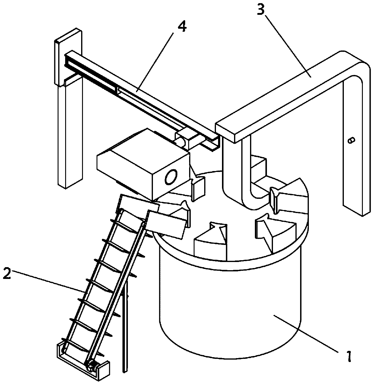
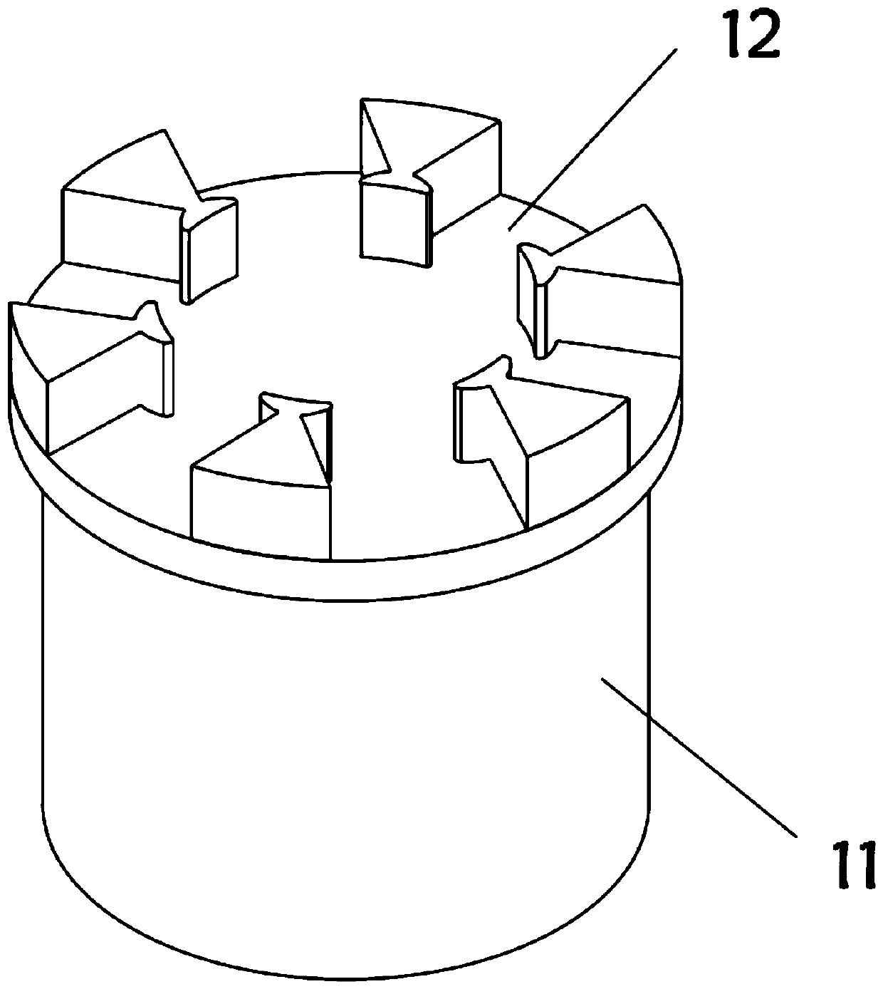
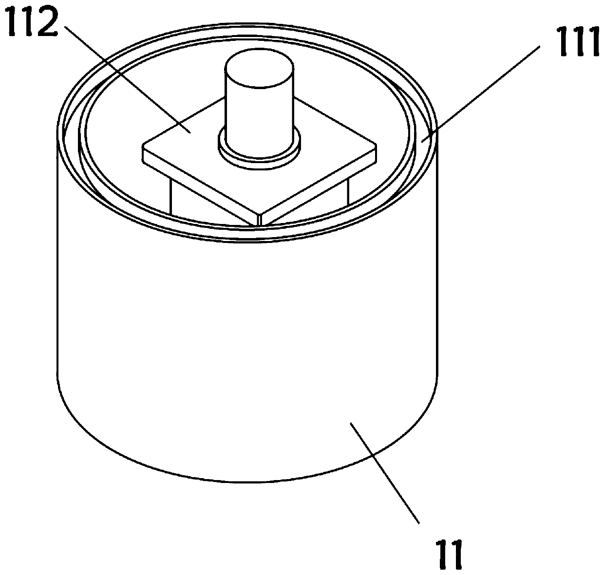
[0043] On the one hand, the present invention provides an integrated loading and unloading two-dimensional code detection device for tobacco rods, such as Figure 1-Figure 5 As shown, it includes a worktable 1, a loading mechanism 2 for loading tobacco rods, a blanking mechanism 3 for blanking tobacco rods, and a detection mechanism 4 for detecting two-dimensional codes on tobacco rods. The workbench 1 includes Support cylinder 11, the top of support cylinder 11 is connected with turntable 12 for rotation, and the top of support cylinder 11 is provided with annular turning groove 111, and the inside of support cylinder 11 is equipped with stepper motor 112, and the top of turntable 12 is installed with a plurality of partitions. block 121, one end of the spacer 121 is integrally formed with a stopper 122, the two sides of the stopper 122 are provided with arc-shaped edges 123, a positioning groove 124 is left between two adjacent spacers 121, and the bottom center position of t...
Embodiment 2
[0051] As the second embodiment of the present invention, in order to facilitate the loading of tobacco rods, the inventors are also provided with a feeding mechanism 2, as a preferred embodiment, such as Image 6 and Figure 7 As shown, the feeding mechanism 2 includes a mounting frame 21 and a blanking plate 22, a pair of side plates 23 are installed between the mounting frame 21 and the blanking plate 22, and drive rollers are respectively installed between the upper and lower ends of the two side plates 23. 24 and the driving roller 25, the side plate 23 is equipped with a working motor 26 near the end of the driving roller 25, a transmission belt 27 is connected between the driving roller 24 and the driving roller 25, and a plurality of receiving plates 28 are installed on the outer wall of the conveyor belt 27. 22 includes a pair of guide plates 221, a bottom plate 222 is installed between the bottoms of the two guide plates 221, and a gap groove 223 is opened on one sid...
Embodiment 3
[0062] As a third embodiment of the present invention, in order to facilitate blanking of tobacco rods, the present invention is also provided with a blanking mechanism 3, as a preferred embodiment, such as Figure 8-Figure 10 As shown, the blanking mechanism 3 includes a support plate 31, the top of the support plate 31 is integrally formed with a top plate 32, the bottom of the top plate 32 is slidingly fitted with a push plate 33, the inner wall of the support plate 31 is equipped with a photoelectric sensor 34, and the inner wall of the top plate 32 is opened. There is a chute 321, one end of the inner wall of the chute 321 is equipped with a first telescopic electric cylinder 322, the push plate 33 includes a connecting plate 331, the top of the connecting plate 331 is provided with a slider 332, and the bottom of the connecting plate 331 is integrally formed with a pushing block 333, One side of the push block 333 is installed with a photoelectric sensor reflection plate ...
PUM
 Abstract
Description
Claims
Application Information
 - R&D
- Intellectual Property
- Life Sciences
- Materials
- Tech Scout
- Unparalleled Data Quality
- Higher Quality Content
- 60% Fewer Hallucinations
Browse by: Latest US Patents, China's latest patents, Technical Efficacy Thesaurus, Application Domain, Technology Topic, Popular Technical Reports.
© 2025 PatSnap. All rights reserved.Legal|Privacy policy|Modern Slavery Act Transparency Statement|Sitemap|About US| Contact US: help@patsnap.com


