Yarn discharging mechanism of yarn double twister

A double-twisting machine and yarn technology, which is applied in the direction of conveying filamentous materials, thin material processing, transportation and packaging, etc. It can solve the problems of slow moving speed, fast yarn winding speed, and the need to improve the reciprocating speed of the wire arrangement mechanism, etc. Problems, achieve the effect of increasing speed, increasing efficiency, and increasing the scope of use

Inactive Publication Date: 2020-04-10
嘉善精田精密机械股份有限公司
View PDF6 Cites 0 Cited by
  • Summary
  • Abstract
  • Description
  • Claims
  • Application Information

AI Technical Summary

Problems solved by technology

[0003] Most of the existing wire arranging mechanisms move left and right through the cooperation of the screw and the nut, which not only requires a forward and reverse motor, but also the moving speed of the screw with the nut is relatively slow, while the winding speed of the yarn is fast, so the existing arranging The round-trip speed of the line mechanism needs to be improved

Method used


Image

  • Yarn discharging mechanism of yarn double twister
  • Yarn discharging mechanism of yarn double twister
  • Yarn discharging mechanism of yarn double twister

Examples


Embodiment 1

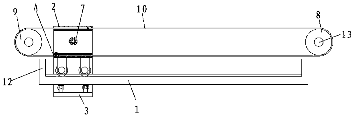
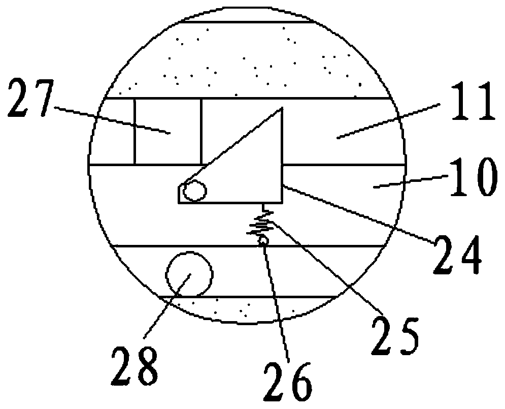
[0035] see Figure 1-6 According to an embodiment of the present invention, a yarn arranging mechanism for a double-twisting machine includes a base 1, on which a mobile terminal 2 is provided, and the mobile terminal 2 includes a mobile seat 3, and the inner wall of the mobile seat 3 passes through The upper roller 4 and the lower roller 5 are connected with the base 1, the number of the upper roller 4 is four, the number of the lower roller 5 is four, and the mobile seat 3 is fixed with a vertical plate 6, The middle part of the vertical plate 6 is provided with a rope hole 7, and the two ends of the base 1 are respectively provided with a driving wheel 8 and a driven wheel 9, and the driving wheel 8 and the driven wheel 9 are connected by a synchronous belt 10. connection, the moving seat 3 and the vertical plate 6 are provided with a synchronous belt through hole 11, the synchronous belt through hole 11 runs through the synchronous belt 10, and the synchronous belt 10 is f...

Embodiment 2

[0038] see Figure 1-8 , for the vertical plate 6, the two ends of the vertical plate 6 are fixedly connected with the upper end of the mobile base 3 through reinforcing ribs 18.

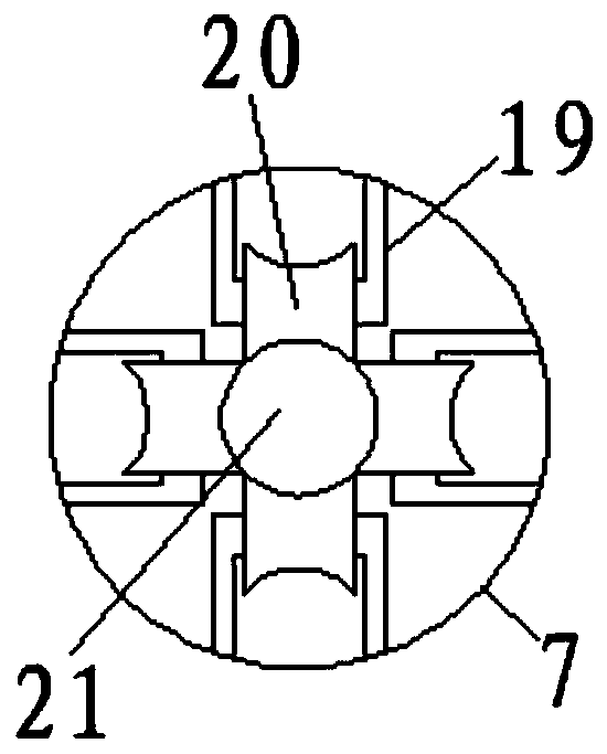
[0039] For the rope-through hole 7 , several sets of brackets 19 are uniformly fixed on the inner wall of the rope-through hole 7 , pulleys 20 are arranged between the brackets 19 , and rope-through gaps 21 are formed between the pulleys 20 .

[0040] For the base 1, two upper rails 22 and lower rails 23 are respectively provided on both sides of the base 1, the upper rail 22 is provided with the upper roller 4, and the lower rail 23 is provided with the Describe lower roller 5.

[0041] Through the above solution of the present invention, the friction force between the yarn and the rope hole 7 can be reduced by setting the pulley 20 , and the moving track of the mobile terminal 2 is restricted by setting the upper track 22 and the lower track 23 .

[0042] For the moving toggle mechanism, the mov...


PUM


Abstract

The invention discloses a yarn discharging mechanism of a yarn double twister. The yarn discharging mechanism comprises a base, and a movable terminal is arranged on the base. The movable terminal comprises a movable seat, and the inner wall of the movable seat is connected with the base through upper rollers and lower rollers. The number of the upper rollers is four, and the number of the lower rollers is four. A stand plate is fixedly arranged on the movable seat, and a rope passing hole is formed in the middle of the stand plate. A driving wheel and a driven wheel are arranged at the two ends of the base correspondingly, and the driving wheel and the driven wheel are connected through a synchronous belt. Synchronous belt through holes are formed in the movable seat and the stand plate,a synchronous belt penetrates through the synchronous belt through holes, and two movable stirring mechanisms are fixedly arranged on the synchronous belt. Blocking mechanisms are arranged in the synchronous belt through holes, and baffles are fixedly arranged at the two ends of the base. The yarn discharging mechanism has the advantages that the yarn discharging speed can be increased, and then the efficiency of enterprises can be improved.

Description

technical field [0001] The invention relates to the field of double-twisting machines, in particular to a yarn arranging mechanism for double-twisting machines. Background technique [0002] The thread arranging mechanism is an important part of the yarn double-twisting machine. Its working principle is that the thread arranging wheel drives the yarn to reciprocate between the spans of the rewinding I-shaped wheel, so that the twisted yarn can be neatly and orderly The winding is on the spool. [0003] Most of the existing wire arranging mechanisms move left and right through the cooperation of the screw and the nut, which not only requires a forward and reverse motor, but also the moving speed of the screw with the nut is relatively slow, while the winding speed of the yarn is fast, so the existing arranging The round-trip speed of the line mechanism needs to be improved. [0004] Aiming at the problems in the related technologies, no effective solution has been proposed ...

Claims


Application Information

Patent Timeline
Patent Type & Authority Applications(China)
IPC IPC(8): B65H54/28
CPCB65H54/28B65H2701/31
Inventor 张红萍
Owner 嘉善精田精密机械股份有限公司
Why Eureka
Try Eureka