Hydrostatic drive transmission system, variable speed control method and loader

A technology of hydrostatic drive and transmission system, which is applied in the field of transmission system, can solve problems such as parking, and achieve the effect of avoiding the impact of shifting

Active Publication Date: 2020-04-10
GUANGXI LIUGONG MASCH CO LTD
View PDF7 Cites 5 Cited by
  • Summary
  • Abstract
  • Description
  • Claims
  • Application Information

AI Technical Summary

Problems solved by technology

[0006] The technical problem to be solved by the present invention is to provide a hydrostatic drive transmission system and a speed change control method for the problem that the existing hydrostatic drive system needs to stop when shifting gears , loader, so that it can realize power shift

Method used


Image

  • Hydrostatic drive transmission system, variable speed control method and loader
  • Hydrostatic drive transmission system, variable speed control method and loader
  • Hydrostatic drive transmission system, variable speed control method and loader

Examples


Embodiment Construction

[0050] The specific implementation will be described below in conjunction with the accompanying drawings.

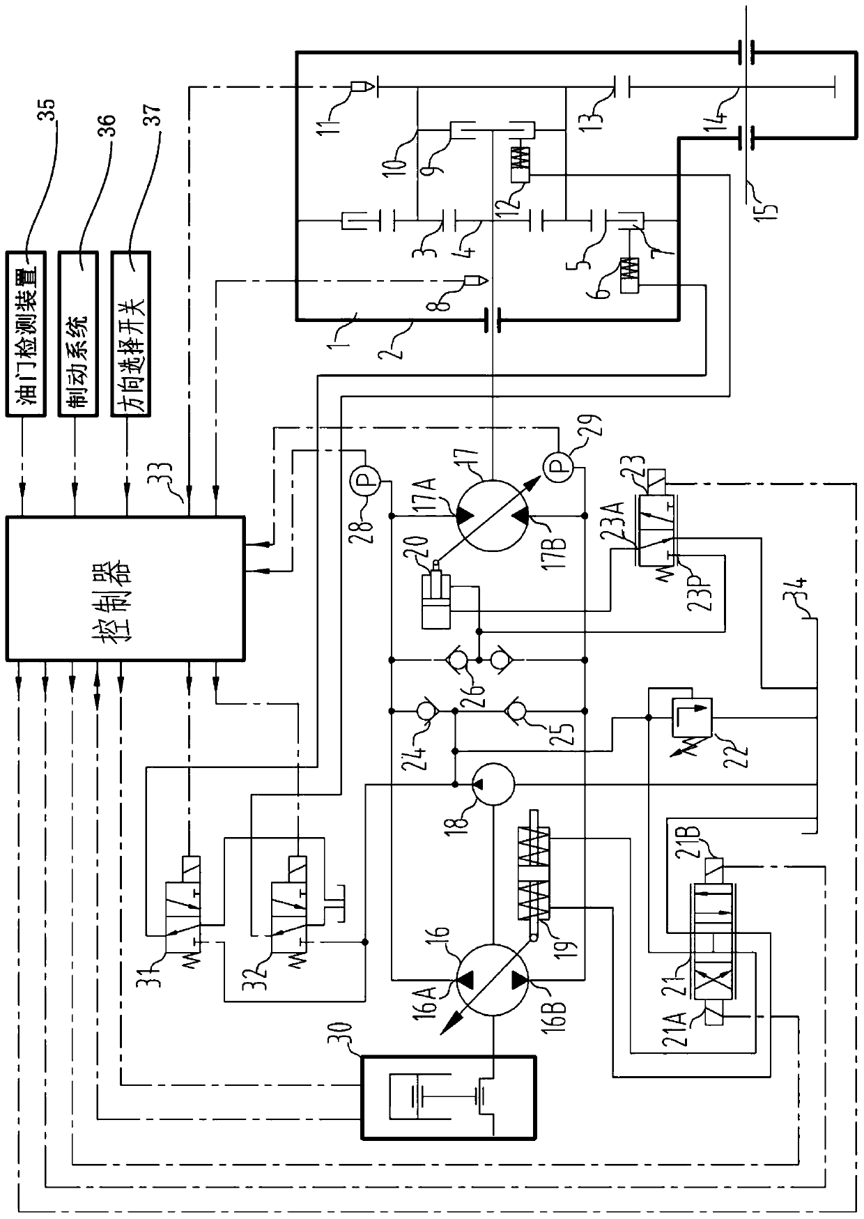
[0051] Such as figure 1 As shown, the hydrostatic drive transmission system in this embodiment is a loader travel drive transmission system. In this transmission system, a closed hydrostatic system drives the rotation of the planetary gearbox. The transmission system includes a two-way variable variable pump 16, a variable motor 17, a two-speed gearbox 1, a shift control unit, an oil charge pump 18, and an oil charge valve;

[0052] The variable displacement pump 16 forms a closed-loop connection with the variable displacement motor 17 through two connected main oil circuits. That is, the A port 16A of the variable displacement pump 16 is connected to the A port 17A of the variable motor 17 through the first main oil passage, and the B port 16B of the variable pump 16 is connected to the B port 17B of the variable motor 17 through the second main oil passage. .

[00...


PUM


Abstract

The invention relates to a hydrostatic drive transmission system, aims to solve the problem that an existing hydrostatic drive system needs to stop during shifting gears, and provides the hydrostaticdrive transmission system, a variable speed control method and a loader. In the hydrostatic drive transmission system, a variable pump is in closed-loop connection with a variable motor, the variablemotor is connected with a gearbox, and a controller outputs control signals used for controlling a pump displacement control solenoid valve, a motor displacement control solenoid valve, a first gear solenoid valve and a second gear solenoid valve correspondingly according to the throttle degree, the gearbox output rotating speed and a direction selection switch signal. The hydrostatic drive transmission system is of single-motor hydrostatic drive, and does not need to stop for shifting gears, during gear shifting, the system has pump displacement compensation control, and gear shifting impactcan be avoided.

Description

technical field [0001] The invention relates to a transmission system, more specifically, to a hydrostatic drive transmission system, a variable speed control method, and a loader. Background technique [0002] The wheel loader is a self-propelled earth-moving machine that completes the work through the cooperation of the walking drive system and the working device, and its walking system provides appropriate traction and speed for the loader's work process. [0003] The walking system of wheel loaders often adopts hydraulic drive, that is, the diesel engine flywheel is connected to the torque converter, and the torque converter is connected to the multi-gear gearbox. . Due to its inherent characteristics, the hydraulic drive system has low transmission efficiency, and the output torque of the hydraulic torque converter can only be adjusted indirectly through the throttle of the diesel engine, and the traction force and vehicle speed cannot be individually adjusted and cont...

Claims


Application Information

Patent Timeline
IPC IPC(8): F16H39/00F16H61/4035F16H61/42F16H61/47
CPCF16H39/00F16H61/4035F16H61/42F16H61/47
Inventor 朱泉明朱斌强杨静霞
Owner GUANGXI LIUGONG MASCH CO LTD
Why Eureka
Try Eureka