A pressure control device for a pneumatic grouting pump

A technology of pressure control and grouting pump, which is applied in the direction of fluid pressure actuators, valve devices, engine components, etc. It can solve the problems of inconvenient use, lower production efficiency, and inaccurate control, etc., and achieve easy use and high grouting efficiency Effect

Active Publication Date: 2021-12-24
江苏江林科技有限公司
View PDF10 Cites 0 Cited by
  • Summary
  • Abstract
  • Description
  • Claims
  • Application Information

AI Technical Summary

Problems solved by technology

[0005] Aiming at the deficiencies of the prior art, the present invention provides a pressure control device for a pneumatic grouting pump, which has the advantages of precise adjustment, etc., and solves the problem of environmental pollution, waste of resources, and inaccurate control during high-pressure control. Reduced production efficiency and inconvenient use

Method used


Image

  • A pressure control device for a pneumatic grouting pump
  • A pressure control device for a pneumatic grouting pump

Examples


Embodiment Construction

[0023] The following will clearly and completely describe the technical solutions in the embodiments of the present invention with reference to the accompanying drawings in the embodiments of the present invention. Obviously, the described embodiments are only some, not all, embodiments of the present invention. Based on the embodiments of the present invention, all other embodiments obtained by persons of ordinary skill in the art without making creative efforts belong to the protection scope of the present invention.

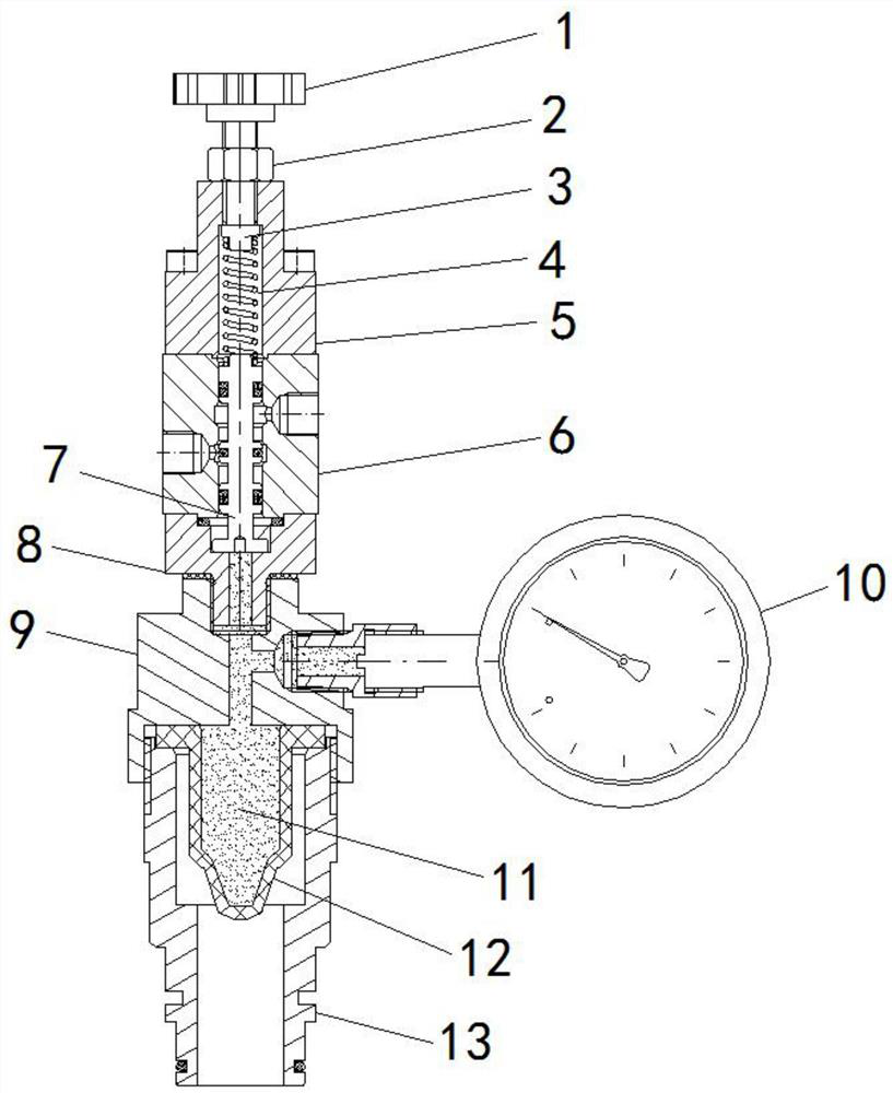
[0024] see Figure 1-2 , a pressure control device for a pneumatic grouting pump, a pressure control device for a pneumatic grouting pump, comprising an adjustment knob 1, the bottom of the outer surface of the adjustment knob 1 is threadedly connected with a lock nut 2, and the bottom of the outer surface of the adjustment knob 1 The valve core gland 5 is threadedly connected, the bottom of the lock nut 2 fits the top of the valve core gland 5, the lock nut 2...


PUM


Abstract

The invention relates to the technical field of pneumatic grouting pumps, and discloses a pressure control device for pneumatic grouting pumps, comprising an adjustment knob, the bottom of the outer surface of the adjustment knob is threaded with a lock nut, and the outer surface of the adjustment knob is The bottom is threadedly connected with a valve core gland, the bottom of the adjustment knob is movably connected with a spring seat, the bottom of the outer surface of the spring seat is clamped with a spring body, and the bottom of the valve core gland is fixedly connected with a valve body, so The inner side of the valve body is movably connected with a valve core body, the bottom of the valve body is fixedly connected with a valve core lower cover, and the bottom of the outer surface of the valve core lower cover is threadedly connected with a diaphragm gland. The pneumatic grouting pump uses a pressure control device to adjust the elastic force of the spring body through the adjustment knob to achieve precise adjustment of the grouting pressure. Using this device, the grouting pressure can be adjusted to a minimum of 0.2MPa, and the control process will not produce pollution. Unlike waste, grouting is more efficient, easy to use, and suitable for a variety of situations.

Description

technical field [0001] The invention relates to the technical field of pneumatic grouting pumps, in particular to a pressure control device for pneumatic grouting pumps. Background technique [0002] The pneumatic grouting pump uses compressed air as the power source, and the cylinder and the grouting cylinder have a larger active area ratio, so that the cylinder can generate a higher injection pressure with a smaller air pressure. [0003] The start and stop of the pneumatic grouting pump is controlled by detecting the grouting pressure, that is, when the grouting pressure reaches the upper limit of the set value, the grouting pump stops working. After the grouting pump stops, the grouting pressure gradually decreases, and when it drops to the set value The grouting pump is turned on immediately when the fixed value is at the lower limit. For example, CN104653424B discloses a pneumatic grouting pump with spring body power-assisted triggering and time-delay reversing. The c...

Claims


Application Information

Patent Timeline
Patent Type & Authority Patents(China)
IPC IPC(8): F16K17/00F16K37/00F15B13/02
CPCF16K17/00F16K37/0091F15B13/02
Inventor 周楚江刘超
Owner 江苏江林科技有限公司
Why Eureka
Try Eureka