
VRV device for machine room

A control method and multi-connection technology, applied in heating and ventilation control systems, air conditioning systems, heating and ventilation safety systems, etc., can solve problems such as insufficient cooling capacity for equipment rooms, shortened life of cooling components, and reduced efficiency of cooling systems, etc. To achieve the effect of reducing the deviation of the operation from the operation curve, reducing the reduction of the operation life and making full use of it

Pending Publication Date: 2020-04-10
YIMIKANG TECH GRP CO LTD +1
View PDF8 Cites 3 Cited by
  • Summary
  • Abstract
  • Description
  • Claims
  • Application Information

AI Technical Summary

Problems solved by technology

[0003] The traditional multi-connected VRV operation system is single, which cannot meet the operation modes of various situations in the equipment room. Generally, the equipment room and subway equipment room are terminally cooled, which is different from the traditional household and commercial multi-connected VRV systems. , without end heating
The main disadvantage of using air-cooled multi-connected VRV devices is that when the temperature is high in summer, the condensation pressure may be too high due to the high outdoor temperature, resulting in a decrease in cooling efficiency, and the cooling capacity does not meet the needs of the equipment room; using a water-cooled system for multi-connected VRV The main disadvantage of the device is that the outdoor temperature is too low in winter, which may lead to low water cooling inlet temperature, resulting in low condensation pressure of the refrigerant when exchanging heat with the refrigerant, which may cause the entire multi-split system to deviate from the system operation. Outside the theoretical pressure curve, long-term operation will reduce the efficiency of the refrigeration system, reduce the life of refrigeration components, and greatly reduce the reliability of the refrigeration system

Method used


Image

  • VRV device for machine room

Examples


Embodiment 1

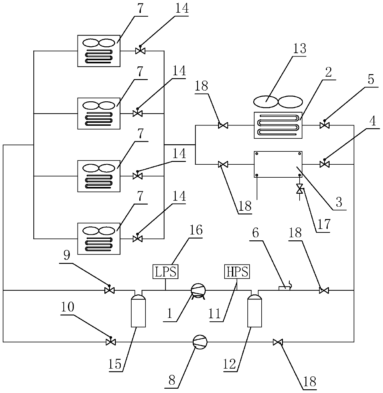
[0040] Embodiment 1: A multi-connected VRV device for a computer room, such as figure 1 As shown, it includes an inverter compressor 1, an air-cooled condenser 2, a water-cooled heat exchanger 3, a water-cooled solenoid valve 4, an air-cooled solenoid valve 5, a temperature sensor 6 and a plurality of terminals 7, and the water-cooled solenoid valve 4 is set on the inverter compressor 1 on the pipeline connected with the water-cooled heat exchanger 3; the air-cooled solenoid valve 5 is set on the pipeline connected with the inverter compressor 1 and the air-cooled condenser 2; the refrigerant inlets of multiple terminals 7 pass through the pipelines to exchange heat with the water-cooled respectively The outlet of the refrigerant in the device 3 and the air-cooled condenser 2 is connected, and the temperature sensor 6 is arranged outdoors to measure the temperature of the outdoor air. Among them, the terminal 7 is an indoor air conditioner, and the number of the terminal 7 can...

Embodiment 2

[0046] Embodiment 2: A multi-connected VRV control method for a computer room, including collecting the outdoor temperature T, and judging the outdoor temperature T and the preset temperature threshold T in real time 1 , T 2 The relationship between, where T 1 ﹥T 2 , if T﹥T 1 , execute the first operation mode; if T≥T 2 and T≤T 1 , execute the first operation mode or the second operation mode; if T2 , the second operation mode is executed; the first operation mode is to control the delivery of the refrigerant to the water-cooled heat exchanger 3 for cooling, and the second operation mode is to control the delivery of the refrigerant to the air-cooled condenser 2 for cooling.

[0047] For the judging process, in this specific implementation, the specific process of judging is not limited, and it can be judged first that T>T 1 , if not, then judge other conditions; you can also judge T≥T first 2 and T≤T 1 , if not, then judge other conditions; you can also judge T2 , if n...

Embodiment 3

[0052]Embodiment 3: A multi-connected VRV system for a computer room, including

[0053] The outdoor temperature collection module is used to collect the outdoor temperature T;

[0054] The first control module judges the outdoor temperature T and the preset temperature threshold T 1 , T 2 The relationship between, where T 1 ﹥T 2 , if T﹥T 1 , execute the first operation mode; if T≥T 2 and T≤T 1 , execute the first operation mode or the second operation mode; if T2 , the second operation mode is executed; the first operation mode is to control the cooling source to be delivered to the water-cooled heat exchanger 3 for cooling, and the second operation mode is to control the cooling source to be delivered to the air-cooled condenser 2 for cooling.

[0055] The outdoor temperature collection module collects the outdoor temperature, and the first control module adopts different operation modes according to different outdoor temperatures. That is, at high temperature, the wa...


PUM


Abstract

The invention relates to a VRV (Variable Refrigerant Volume) device for a machine room, a control method and a system. The VRV device comprises an inverter compressor, an air-cooled condenser, a water-cooled heat exchanger, a water-cooled electromagnetic valve, an air-cooled electromagnetic valve, a temperature sensor and a plurality of tail ends, and the water-cooled electromagnetic valve is arranged on a pipeline for communicating the inverter compressor with the water-cooled heat exchanger; the air-cooled electromagnetic valve is arranged on a pipeline for communicating the inverter compressor with the air-cooled condenser; the tail ends respectively communicate with the outlets of refrigerants in the water-cooled heat exchanger and the air-cooled condenser through pipelines, and the temperature sensor is arranged outdoors and is used for measuring the temperature of outdoor air. The refrigeration efficiency of the tail ends is improved, and the shutdown risk of the VRV is reduced;operation deviation of the refrigeration system from the operation curve of the system is reduced, service life reduction of refrigeration components is reduced, and the advantages of improving the efficiency of the refrigeration system and reliability of the refrigeration system are achieved.

Description

technical field [0001] The invention relates to the field of multi-connection cooling for computer rooms, in particular to a multi-connection VRV device, control method and system for computer rooms. Background technique [0002] At present, the growing demand for energy saving, emission reduction and green environmental protection worldwide has put forward higher demands on the energy consumption and cooling capacity of subway operations and IT industry data centers; the reliability and stability of energy saving and refrigeration system operation have become Top of mind for homeowners and design builders. [0003] The traditional multi-connected VRV operation system is single, which cannot meet the operation modes of various situations in the equipment room. Generally, the equipment room and subway equipment room are terminally cooled, which is different from the traditional household and commercial multi-connected VRV systems. , without end heating. The main disadvantag...

Claims


Application Information

Patent Timeline
Patent Type & Authority Applications(China)
IPC IPC(8): F25B1/00F25B41/04F25B49/02F24F3/06F24F11/64F24F11/65F24F11/83F24F110/12F24F140/12F25B41/20
CPCF25B1/00F25B49/02F24F3/065F24F11/64F24F11/65F24F11/83F24F2110/12F24F2140/12F25B41/20
Inventor 范玉斐张菀向文李猛田珊卓小军马晓林
Owner YIMIKANG TECH GRP CO LTD
Learn More