[0027] In order to make the objectives, technical solutions and advantages of the present invention clearer, the following further describes the present invention in detail with reference to the accompanying drawings and embodiments. It should be understood that the specific embodiments described herein are only used to explain the present invention, but not to limit the present invention. In addition, the technical features involved in the various embodiments of the present invention described below can be combined with each other as long as they do not conflict with each other.
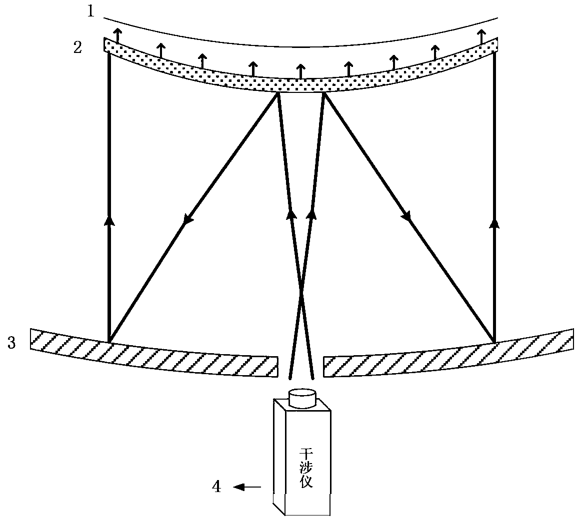
[0028] The invention discloses a method for performing full-aperture compensation measurement on a convex free-form surface mirror based on a spherical surface mirror and a curved surface computed hologram, and solves the problem that the large-aperture convex free-form surface mirror surface is difficult to measure in full-aperture interference. This method realizes the zero compensation of the convex free-form surface mirror by combining the curved surface computed hologram and the spherical surface mirror. Moreover, in order to realize the precise alignment of the interferometer, the curved computed hologram, the spherical mirror and the convex free-form surface mirror to be tested in the detection light path, the corresponding functional area is designed on the curved computed hologram. The curved computed hologram contains a total of There are four diffraction areas, namely the interferometer alignment area on the convex surface, the main detection area on the concave surface, the crosshair projection area and the spherical mirror alignment area. The above four areas together ensure the detection of optical elements in the optical path Accurate alignment and accurate measurement of free-form surface shape results.
[0029] The measurement method of the present invention will be described below in conjunction with specific embodiments. figure 1 Shown is a large-aperture convex free-form surface mirror surface-shaped interference detection optical path diagram. In interference detection, a spherical mirror and a curved surface computer hologram are used to perform full-aperture compensation measurement on the free-form surface to achieve zero detection, that is, each incident light They are incident along the normal line of the free-form surface mirror, and emitted along the normal line. Specifically, the detection optical path involves the convex free-form surface mirror to be tested 1, the curved surface computed hologram figure 2 , The spherical mirror 3 and the interferometer 4 are four optical elements, in which the front and back surfaces of the curved computed hologram are spherical.
[0030] The misalignment of the optical elements in the optical path will cause additional aberrations to be introduced in the detection results. Therefore, in order to ensure the precise alignment between the optical elements during the detection, the hologram is calculated on the curved surface. figure 2 Design the corresponding alignment area on the figure 2 As shown, the interferometer alignment area A1 and the convex blocking reflection area A2 are designed on the convex part of the curved computer hologram, and the spherical mirror alignment area B1, the cross-hair projection area B2, and the main surface are designed on the concave part of the curved computer hologram. Detection area B3. The interferometer alignment area A1 is located at the center of the convex part of the curved computer hologram to complete the curved computer hologram figure 2 Precise alignment with the interferometer 4; the spherical mirror alignment area B1 is located at the periphery of the main detection area B3, and is used for curved computed holography figure 2 Accurate alignment with spherical mirror 3.
[0031] During inspection, first use the interferometer to align the area A1 to complete the curved surface CGH figure 2 Precise alignment with interferometer 4: Computed holography by adjusting the curved surface figure 2 The relative position with the interferometer 4 (including three-dimensional translation and tilt), so that the light emitted by the interferometer 4 is reflected by the interferometer alignment area A1 and then returns to the interferometer 4, and forms interference fringes with the interferometer reference light, continue to adjust The relative position of the curved computed hologram and the interferometer, adjust the interference fringe to the zero fringe state (the interference fringe is all black or all white, such as image 3 Shown), at this time, the interferometer 4 and the curved CGH figure 2 Complete precise alignment.
[0032] After finishing interferometer 4 and curved surface CGH figure 2 After the alignment, place the spherical mirror 3 and adjust its position. At this time, the interferometer 4 emits light through the curved surface CGH figure 2 The convex part is reflected to the spherical mirror 3, and then reflected to the curved surface computed hologram by the spherical mirror 3 figure 2 The convex surface is reflected by the spherical mirror aligning area B1 on the concave surface of the curved computed hologram and then returns to the interferometer 4 along the original path, and forms interference fringes with the interferometer reference light. Continue to adjust the position of the spherical mirror 3 to interfere Adjust the fringe to the zero fringe state, at this time the interferometer 4, the spherical mirror 3 and the curved computer hologram figure 2 It is precisely aligned.
[0033] In the completion of interferometer 4, spherical mirror 3 and curved CGH figure 2 After the precise alignment, the computed hologram on the curved surface figure 2 Four cross lines will be formed behind the Figure 4 Shown. Place the free-form surface mirror 1 in the center of the four crosses. At this time, the rough alignment of the free-form surface mirror in the optical path is completed. It will form a corresponding interference in the interferometer 4 through the main detection area B3 of the curved surface computed hologram stripe. Then, the position (translation and tilt) of the convex free-form surface mirror 1 is further adjusted, the free-form surface detection interference fringes formed in the interferometer 4 will become sparse and even zero fringes can be obtained. At this time, the free-form surface is completed The precise adjustment of the reflector in the optical path realizes the interferometer 4, the curved computer hologram figure 2 , The precise alignment of the spherical mirror 3 and the convex free-form surface mirror 1. At this time, the wave aberration results of the corresponding free-form surface mirror can be measured, and the precise position of the free-form surface mirror can be adjusted according to the aberration to realize a large-diameter free-form surface. The zero compensation measurement of the mirror finally obtains the mirror surface interference detection result of the large-aperture convex free-form surface mirror.
[0034] Those skilled in the art can easily understand that the above descriptions are only preferred embodiments of the present invention and are not intended to limit the present invention. Any modification, equivalent replacement and improvement, etc. made within the spirit and principle of the present invention, All should be included in the protection scope of the present invention.