Supercharge Your Innovation With Domain-Expert AI Agents!

Installation and adjustment device and method for birefringent interferometer based on optical path difference indication

An adjustment method and birefringence technology, which is applied in the direction of interference spectroscopy, measuring devices, optical radiation measurement, etc., can solve problems such as difficulty in meeting the requirements for the accuracy of interferometer installation and adjustment, and achieve reduced adjustment errors, high adjustment sensitivity, The effect of improving the degree of modulation

Active Publication Date: 2021-01-15
XI'AN INST OF OPTICS & FINE MECHANICS - CHINESE ACAD OF SCI
View PDF4 Cites 0 Cited by
  • Summary
  • Abstract
  • Description
  • Claims
  • Application Information

AI Technical Summary

Problems solved by technology

[0004] The purpose of the present invention is to provide a birefringent interferometer installation and adjustment method based on optical path difference indication to solve the problem that the existing birefringence interferometer installation and adjustment method based on interference fringe indication is difficult to meet the dual Technical issues of interferometer adjustment accuracy requirements for refraction polarization interference type hyperspectral imaging devices

Method used


Image

  • Installation and adjustment device and method for birefringent interferometer based on optical path difference indication
  • Installation and adjustment device and method for birefringent interferometer based on optical path difference indication
  • Installation and adjustment device and method for birefringent interferometer based on optical path difference indication

Examples


Embodiment Construction

[0042] The present invention will be described in detail below in conjunction with the accompanying drawings and specific embodiments.

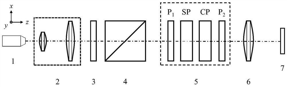
[0043] see figure 1, a birefringent interferometer installation and adjustment device based on optical path difference indication in the present invention, the birefringence interferometer 5 to be adjusted includes prepolarizers P sequentially arranged along the optical path 1 , birefringent shear plate SP, birefringent compensation plate CP and analyzer P 2 The structure of the installation and adjustment device includes a laser light source 1, a beam expander system 2, a diffuser 3, a standard polarizer 4, an imaging objective lens 6 and a detector 7 arranged in sequence along the optical path.

[0044] Definition: the direction of the reflected light path of the standard polarizer 4 is the positive direction of the x-axis, the direction of the transmitted light path of the standard polarizer 4 is the positive direction of the z-axis, and ...


PUM

PropertyMeasurementUnit
wavelengthaaaaaaaaaa

Abstract

The invention relates to a birefringent interferometer adjusting device and an adjusting method, in particular to a birefringent interferometer adjustment device and adjustment method based on opticalpath difference indication, and solves the technical problem that the existing birefringent interferometer adjustment device and adjustment method based on interference fringe indication are difficult to meet the requirement of birefringent polarization interference type hyperspectral imaging device interferometer adjustment precision. The adjusting device is characterized by comprising a laser light source, a beam expanding system, a scatterer, a standard polarizer, an imaging objective lens and a detector which are sequentially arranged along a light path, wherein the reflection light pathdirection of the standard polarizer is the x-axis forward direction, the transmission light path direction of the standard polarizer is the z-axis forward direction, and the normal direction of a plane determined by the x-axis and the z-axis is the y-axis direction; the transmission light polarization direction of the standard polarizer is parallel to the x axis; the detector is located at the rear focal plane of the imaging objective lens. The invention further provides an assembling and adjusting method based on the assembling and adjusting device.

Description

technical field [0001] The invention relates to a birefringence interferometer installation and adjustment device and an installation method, in particular to a birefringence interferometer installation and adjustment device and an installation method based on optical path difference indication. Background technique [0002] Interferometric hyperspectral imaging technology is based on the modulation relationship between signals, and performs Fourier transform processing on the interference signal, which can be demodulated to obtain the spectral signal of the detection target. The key to obtaining an ideal interference signal is to adjust the core component interferometer with high precision to minimize the impact of adjustment errors. Birefringent interferometric hyperspectral imaging devices have been widely used in the field of spectral measurement due to their compact structure and simple optical path. The core component of this type of device is the birefringent interfe...

Claims


Application Information

Patent Timeline
Patent Type & Authority Patents(China)
IPC IPC(8): G01J3/45G01J3/28
CPCG01J3/0224G01J3/2823G01J3/45G01J2003/2826
Inventor 柏财勋冯玉涛范文慧李立波李海巍畅晨光胡炳樑
Owner XI'AN INST OF OPTICS & FINE MECHANICS - CHINESE ACAD OF SCI
Features
  • R&D
  • Intellectual Property
  • Life Sciences
  • Materials
  • Tech Scout
  • Unparalleled Data Quality
  • Higher Quality Content
  • 60% Fewer Hallucinations
Learn More