
Loading device for overall stability test of horizontal steel curved beam

A technology of stability test and loading device, applied in the direction of applying stable tension/pressure to test material strength, measuring device, strength characteristics, etc., can solve problems such as lateral deformation of horizontal steel curved beams, and improve test accuracy , Guarantee the safety of the experiment, the effect of optimizing the structure and installation method

Active Publication Date: 2020-04-10
HUAZHONG UNIV OF SCI & TECH
View PDF7 Cites 1 Cited by
  • Summary
  • Abstract
  • Description
  • Claims
  • Application Information

AI Technical Summary

Problems solved by technology

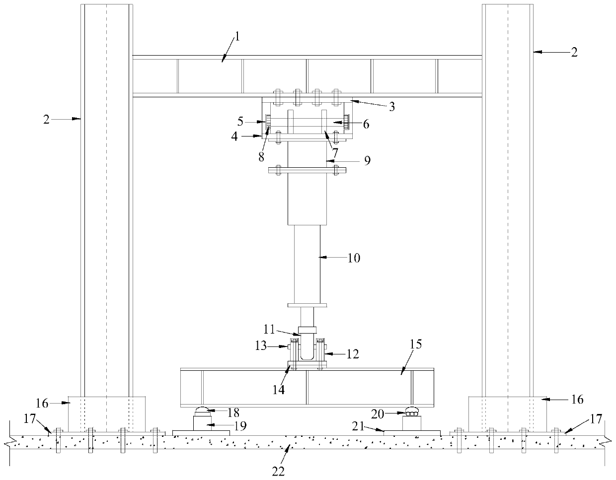
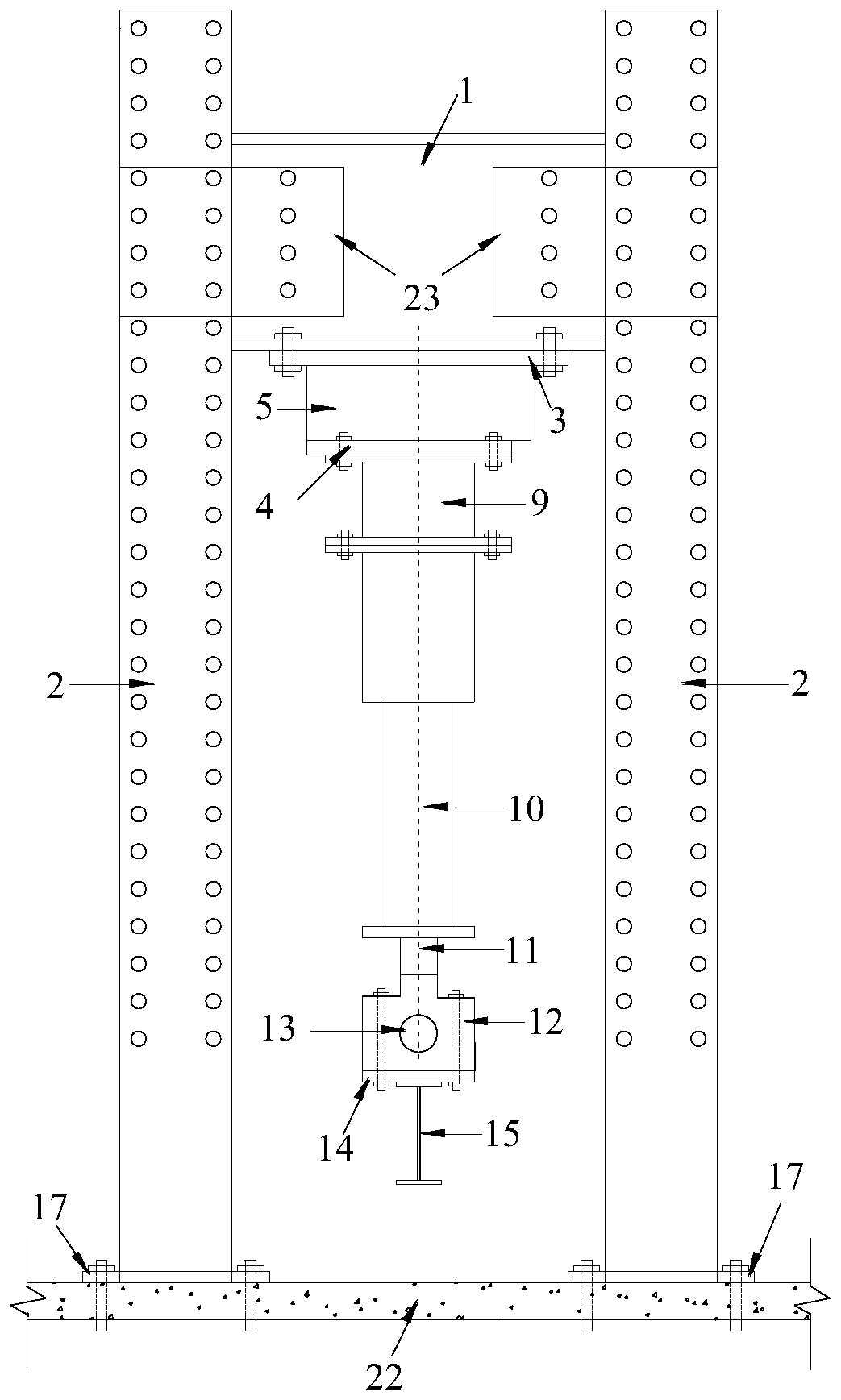
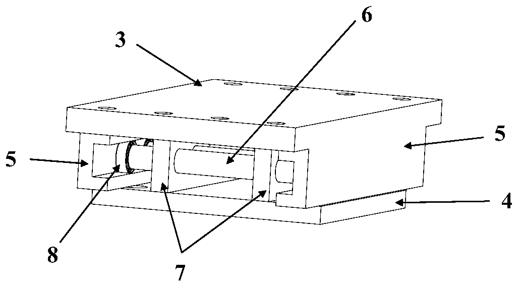
[0005] Aiming at the above defects or improvement needs of the prior art, the present invention provides a loading device for the overall stability test of the horizontal steel curved beam, wherein in combination with the problem that the horizontal steel curved beam is prone to lateral deformation, the corresponding reaction force A sliding unit is designed between the frame unit and the pressure sensor, so as to drive the pressure sensor and the loading unit to slide along the length direction perpendicular to the horizontal steel curved beam, so as to ensure that the horizontal steel curved beam can still be supported by the vertical downward force when it is displaced laterally. Load, so it is especially suitable for the application occasion of the overall stability test of the horizontal steel curved beam

Method used


Image

  • Loading device for overall stability test of horizontal steel curved beam
  • Loading device for overall stability test of horizontal steel curved beam
  • Loading device for overall stability test of horizontal steel curved beam

Examples


Embodiment Construction

[0029] In order to make the object, technical solution and advantages of the present invention clearer, the present invention will be further described in detail below in conjunction with the accompanying drawings and embodiments. It should be understood that the specific embodiments described here are only used to explain the present invention, not to limit the present invention. In addition, the technical features involved in the various embodiments of the present invention described below can be combined with each other as long as they do not constitute a conflict with each other.

[0030] Such as Figure 1~3 As shown, the embodiment of the present invention provides a loading device for the overall stability test of a horizontal steel curved beam, the loading device includes a reaction force frame unit, a sliding unit, a pressure sensor 9 and a loading unit, wherein:

[0031] The reaction force frame unit includes a reaction force column 2 and a reaction force beam 1, the...


PUM


Abstract

The invention belongs to the related technical field of steel structures, and particularly discloses a loading device for overall stability test of a horizontal steel curved beam. The loading device comprises a counter-force frame unit, a sliding unit, a pressure sensor and a loading unit, wherein the counter-force frame unit is used for supporting the loading device; a top flat plate of the sliding unit is connected to the counter-force frame unit, sliding grooves are fixed to the left side and the right side of the top flat plate, and a sliding assembly is connected to a bottom flat plate and drives the bottom flat plate to slide in the length direction perpendicular to the horizontal steel curved beam. The upper side of the pressure sensor is connected to the bottom flat plate, and thelower side is connected to the loading unit. According to the invention, the sliding unit is arranged between the counter-force frame unit and the pressure sensor, when the horizontal steel curved beam generates lateral displacement, the pressure sensor and the loading unit can be driven to slide in the direction perpendicular to the length direction of the horizontal steel curved beam, so that the loading direction is always vertically downward in the loading process, and meanwhile, the constraint on the lateral displacement of the horizontal steel curved beam is released.

Description

technical field [0001] The invention belongs to the technical field related to steel structures, and more specifically relates to a loading device for the overall stability test of horizontal steel curved beams. Background technique [0002] In recent years, due to its beautiful shape and good mechanical properties, curved beams have been used more and more frequently in construction and bridge engineering. As a bending member, the stability of steel curved beams is the most prominent problem. In bridge engineering, the lateral load is often large and the dynamic load dominates, which puts forward higher requirements for the stability of the curved beam. Therefore, it is necessary to conduct experimental research on the overall stability of horizontal steel curved beams. [0003] At present, there are few experimental studies on the overall stability of horizontal steel curved beams at home and abroad. The main reason is that when curved beams bear lateral loads, they will ...

Claims


Application Information

Patent Timeline
IPC IPC(8): G01N3/08
CPCG01N3/08G01N2203/0003G01N2203/0019
Inventor 高飞左国稷邵永波邓丽霞杨帆陈潘
Owner HUAZHONG UNIV OF SCI & TECH
Learn More