Winding machine for winding metal foil type capacitor

A capacitor and winding machine technology, applied in winding capacitor machines and other directions, can solve the problems of cumbersome processes and low efficiency, and achieve the effect of optimizing the overall layout

Pending Publication Date: 2020-04-10
常州联威自动化设备有限公司
View PDF0 Cites 2 Cited by
  • Summary
  • Abstract
  • Description
  • Claims
  • Application Information

AI Technical Summary

Problems solved by technology

[0002] At present, the wound foil capacitor uses a semi-automatic winding machine. When inserting the aluminum foil, it is necessary to manually fold the two ends of the aluminum foil. The process is cumbersome and the efficiency is low.

Method used


Image

  • Winding machine for winding metal foil type capacitor
  • Winding machine for winding metal foil type capacitor

Examples


Embodiment

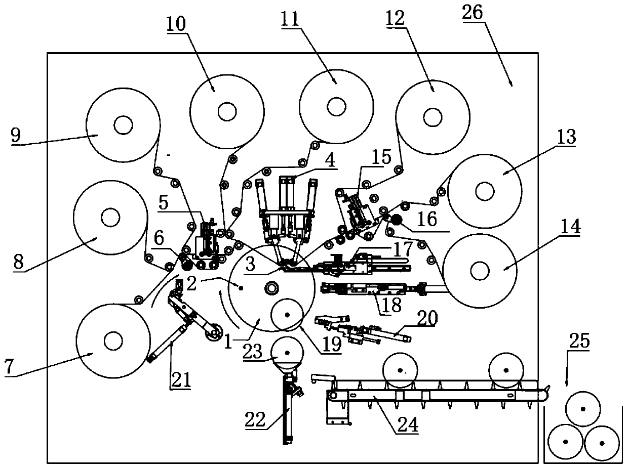
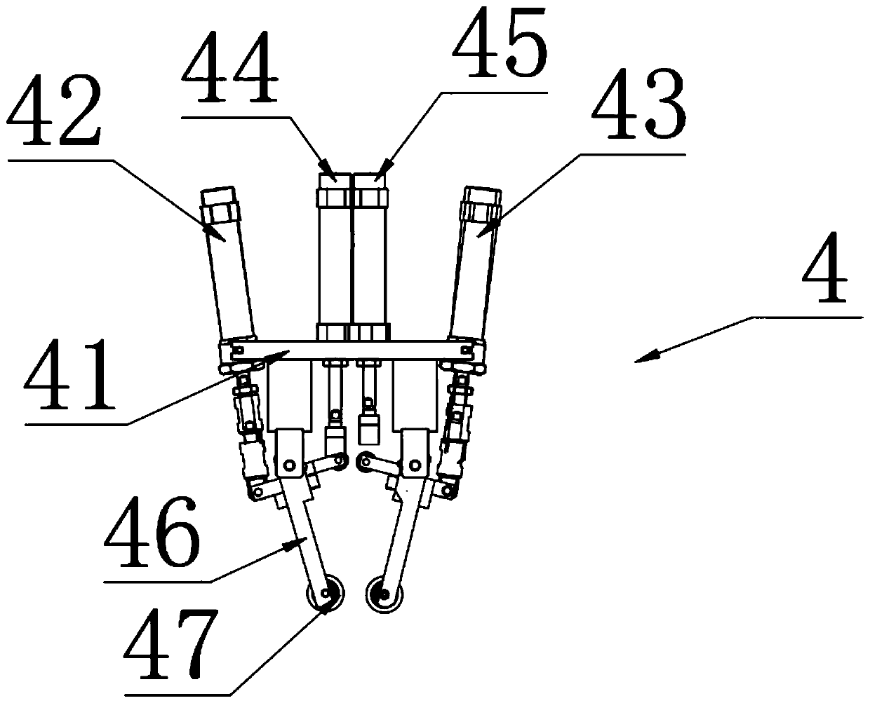
[0020] like Figure 1-2 As shown, a winding machine for winding metal foil capacitors includes a base plate 26 on which a machine head mechanism 1 is arranged, and station one 2, station two 3 and station three 19 are respectively located on the machine Circumferential direction of head mechanism 1 top, on its station all be inserted with rolling pin, the outer wall of described station two 3 is connected with the inner wall of one end of pressure roller mechanism 4, and between described station two 3 and roller mechanism 4, set There is a material insertion mechanism 17, and the end of the pressure wheel mechanism 4 away from the material insertion mechanism 17 is provided with a No. 1 hemming mechanism 5, and a No. 1 one-way wheel mechanism 6 is provided below the No. 1 hemming mechanism 5, and a material tray 7 , material disc two 8, material disc four 10, material disc five 11, material disc six 12 and material disc eight 14 are all located in the circumferential directio...


PUM


Abstract

The invention discloses a winding machine for winding a metal foil type capacitor. The winding machine comprises a substrate, a machine head mechanism is arranged on the substrate; a first station, asecond station and a third station are located in the circumferential direction of the machine head mechanism. A winding needle is inserted into each station; a material inserting mechanism is arranged between the second station and a pressing wheel mechanism. A first edge folding mechanism is arranged at one end of the pressing wheel mechanism. A first one-way wheel mechanism is arranged below the first edge folding mechanism; all the material discs are located in the circumferential direction of the machine head mechanism, roughened films (OPP) on the material discs penetrate through pressing wheels of a pressing wheel mechanism through rolling wheels along a material film path and are wound on winding needles of a second station, and aluminum foil on a third material disc and aluminum foil on a seventh material disc pass through rolling wheels and a first edge folding mechanism and are wound into winding needles of the second station along an aluminum foil path. The overall layout of a thin film and aluminum foil winding path of the foil type capacitor winding machine is optimized, capacitors of different specifications are produced, and a mechanism for automatically feeding a hard core rod is adopted in the first station, so that the equipment can operate in a full-automatic mode.

Description

technical field [0001] The invention relates to a winding machine for winding metal foil capacitors, belonging to the technical field of winding machines. Background technique [0002] At present, the coiled foil capacitor uses a semi-automatic winding machine. When inserting the aluminum foil, it is necessary to manually fold the two ends of the aluminum foil. The process is cumbersome and the efficiency is low. Contents of the invention [0003] The technical problem to be solved by the present invention is to overcome the defects of the prior art and provide a winding machine for winding metal foil capacitors. [0004] In order to solve the problems of the technologies described above, the present invention provides the following technical solutions: [0005] A winding machine for winding metal foil capacitors according to the present invention includes a substrate, on which a head mechanism is arranged, and station 1, station 2 and station 3 are respectively located i...

Claims


Application Information

Patent Timeline
Patent Type & Authority Applications(China)
IPC IPC(8): H01G13/02
CPCH01G13/02
Inventor 陈中威
Owner 常州联威自动化设备有限公司
Why Eureka
Try Eureka