Occluders and Closure Systems
A technology of occluder and occluder disk, which is applied in medical science, surgery, etc., can solve the problem of slow endothelialization of the surface of the occluder, and achieve the effect of avoiding wear and accelerating surface endothelialization
- Summary
- Abstract
- Description
- Claims
- Application Information
AI Technical Summary
Problems solved by technology
Method used
Image
Examples
no. 1 example
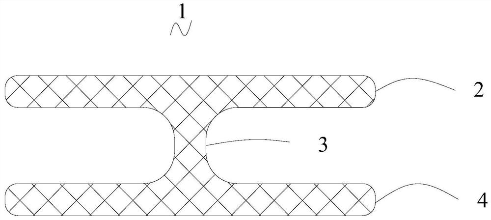
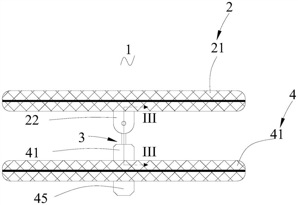
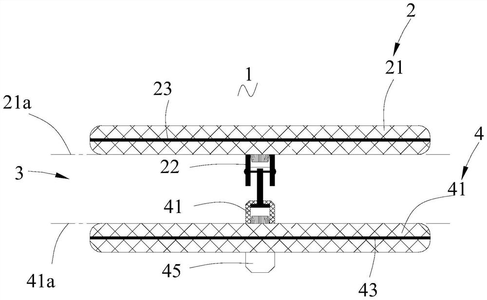
[0045] see figure 2 In this embodiment, an occluder 1 is provided, including a first occlusion disk 2 , a waist structure 3 and a second occlusion disk 4 . The waist structure 3 is arranged between the first occlusion disk 2 and the second occlusion disk 4, that is, the distal end of the waist structure 3 is located on the proximal side of the distal end surface of the first occlusion disk 2, and the proximal end of the waist structure 3 is located on the The distal side of the distal end face of the second occlusion disc 4 . The first blocking disk 2 is connected with the second blocking disk 4 through the waist structure 3 .
[0046] see image 3, the first plugging disk 2 includes a grid structure 21 , a first plug head 22 and a first choke film 23 . The first plug disc 2 is provided with a first plug head 22 at its proximal end, that is, the first plug head 22 is fixed to the proximal end of the grid structure 21, and the first flow blocking film 23 is arranged in the ...
no. 2 example
[0077] see Figure 10 The difference between this embodiment and the first embodiment is that the distal end of the first part 321 includes a connecting ring 341 , and the second connecting member 32 is rotatably connected with the first connecting member 31 through the connecting ring 341 . The outer diameter of the connecting ring 341 is greater than the diameter of the first part 321, so that the first connecting member 31 does not have to make its outer diameter smaller than the aperture of the perforating hole 3211 in order to be able to rotatably fit into the through hole 3211, and then the first connecting member 31 can be effectively reduced. risk of breakage.
[0078] see Figure 11 , the first part 321 and the second part 322 are detachably connected or fixedly connected. In this embodiment, preferably, the first part 321 is detachably connected to the second part 322 , for example, the first part 321 is connected to the second part 322 through threads. see Figu...
no. 3 example
[0080] see Figure 13 The difference between this embodiment and the first embodiment is that two sliding grooves 227 are provided on the inner wall of the cavity 226, and the two sliding grooves 227 are opposite to each other. Preferably, the two sliding grooves 227 are opposite to each other along the diameter of the through cavity 226 . The two sliding grooves 227 extend from the distal end of the first bolt head 22 to the proximal end of the first bolt head 22, and the extension length of the first bolt head 22 is less than the axial length of the first bolt head 22, that is, the two sliding grooves 227 Through the proximal end of the first plug head 22 . When the first connecting piece 31 is connected with the first bolt head 22, the two ends of the first connecting piece 31 slide into a sliding groove 227 correspondingly, thereby realizing the movable connection between the first connecting piece 31 and the first bolt head 22, The first connecting member 31 can slide i...
PUM
 Abstract
Description
Claims
Application Information
 - R&D
- Intellectual Property
- Life Sciences
- Materials
- Tech Scout
- Unparalleled Data Quality
- Higher Quality Content
- 60% Fewer Hallucinations
Browse by: Latest US Patents, China's latest patents, Technical Efficacy Thesaurus, Application Domain, Technology Topic, Popular Technical Reports.
© 2025 PatSnap. All rights reserved.Legal|Privacy policy|Modern Slavery Act Transparency Statement|Sitemap|About US| Contact US: help@patsnap.com


