
Mold pressing forming device used for producing base of power distribution cabinet and using method thereof

A power distribution cabinet base, molding technology, applied in the direction of switchgear, electrical components, etc., can solve the problems of manual unloading of workers, irritating smell and high temperature, etc., to achieve high safety, improve safety, and simple operation.

Inactive Publication Date: 2020-04-14
广州市顺承电气设备有限公司
View PDF3 Cites 1 Cited by
  • Summary
  • Abstract
  • Description
  • Claims
  • Application Information

AI Technical Summary

Problems solved by technology

[0003] Generally, the base of the power distribution cabinet is formed by plastic molding, but the general molding equipment is manually unloaded by workers when unloading. After the base of the power distribution cabinet under high temperature is processed, there will be pungent smell and High temperature, and work under high pressure equipment must pay great attention to safety

Method used


Image

  • Mold pressing forming device used for producing base of power distribution cabinet and using method thereof
  • Mold pressing forming device used for producing base of power distribution cabinet and using method thereof
  • Mold pressing forming device used for producing base of power distribution cabinet and using method thereof

Examples


Embodiment 1

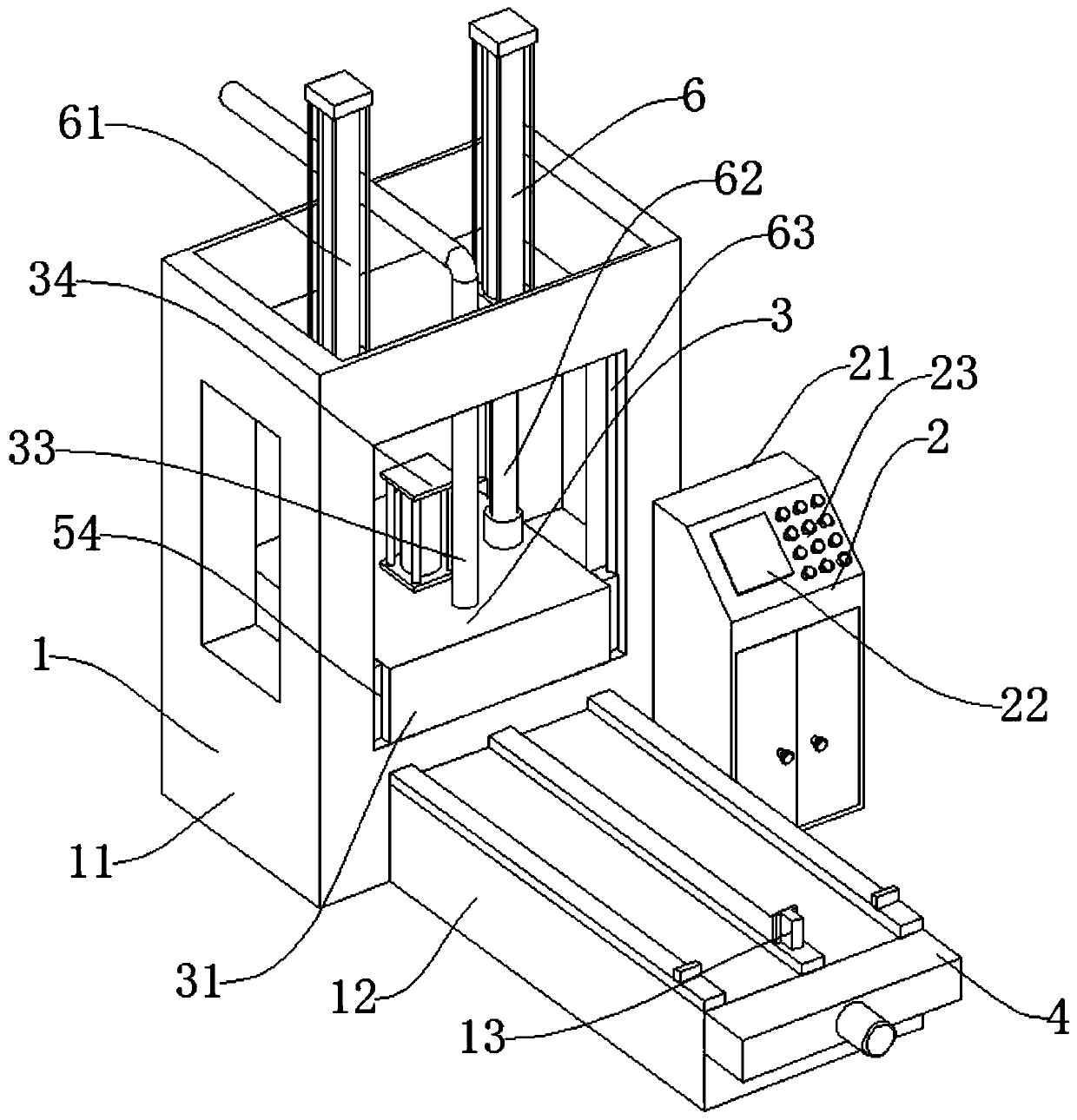
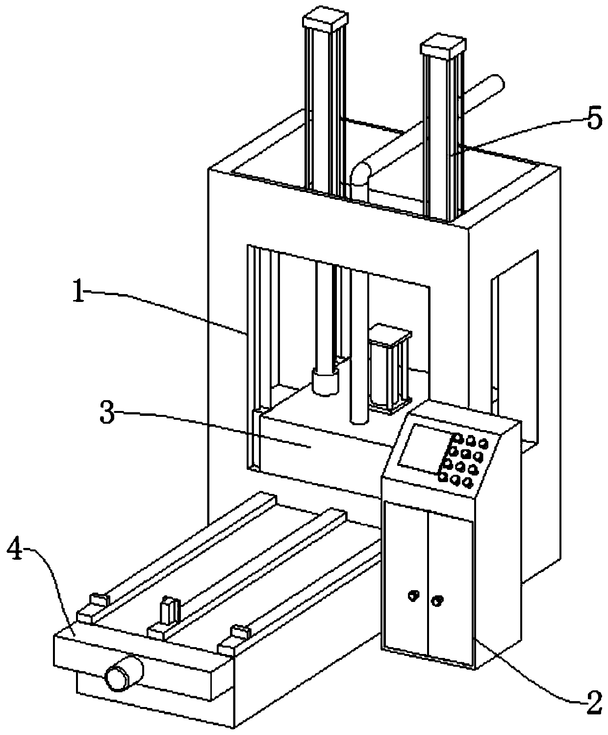
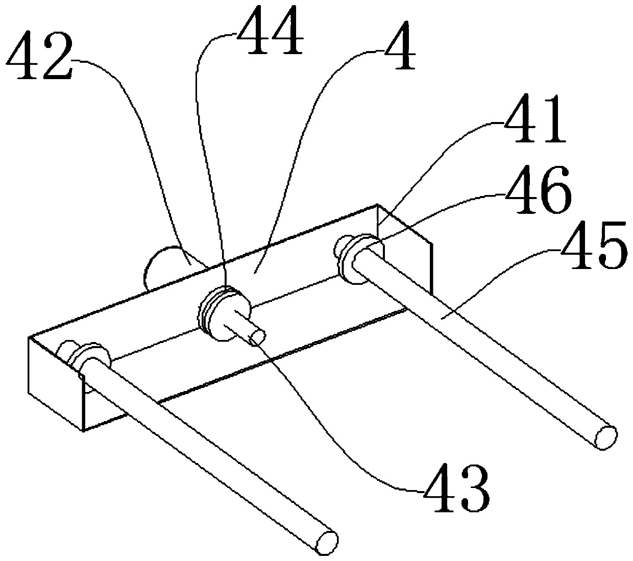
[0045] like figure 1 , figure 2 , image 3 , Figure 4As shown, the pushing mechanism 5 includes an L-shaped push plate 51, a first slider 52, and a limit groove 53. The first slider 52 is connected to the screw 45 of the power mechanism 4, and the upper end of the first slider 52 is connected to the L-shaped push plate 51. , the first slider 52 and the support frame 11 of the support mechanism 1 are provided with a limit groove 53, the L-shaped push plate 51 acts as a pusher, and the first slider 52 acts as a linkage; the power mechanism 4 includes a fixed box 41, a motor 42, the central shaft 43, the driving sprocket 44, the support frame 11 or the receiving frame 12 that the fixed box 41 is connected to the support mechanism 1, the fixed box 41 is provided with a motor 42, the motor 42 is connected with the central shaft 43, and the central shaft 43 is provided with Two driving sprockets 44, both sides of the central shaft 43 are provided with screw rods 45, the screw r...

Embodiment 2

[0047] like figure 1 , figure 2 , image 3 , Figure 5 , Image 6 As shown, the difference between this embodiment and Embodiment 1 is: preferably: the pushing mechanism 5 includes a second slider 511, a column 512, a horizontal plate 513, a connecting pin 514, and the second slider 511 is connected to the screw rod of the power mechanism 4 45. The upper end of the second slider 511 is connected to the column 512, the rear end of the column 512 is connected to the horizontal plate 513, the inner side of the horizontal plate 513 is provided with a connecting pin 514, and the lower end of the connecting pin 514 is provided with a hook bar 515, between the hook bar 515 and the horizontal plate 513 A storage slot 516 is provided, the second slider 511 acts as a linkage, and the hook bar 515 acts as a hook.

[0048] A method for using a molding device for producing a base of a power distribution cabinet includes the following steps:

[0049] a. When processing is required, fi...


PUM


Abstract

The invention discloses a mold pressing forming device used for producing a base of a power distribution cabinet and a using method thereof. The mold pressing forming device comprises a supporting mechanism, a control structure, a mold pressing mechanism and a lifting mechanism. The control structure is arranged on one side of the supporting mechanism. The mold pressing mechanism is arranged at the upper end of the supporting mechanism. The lifting mechanism is arranged at the upper end of the mold pressing mechanism. The mold pressing forming device further comprises a pushing mechanism usedfor retreating materials and a power mechanism used for driving the pushing mechanism to operate. The mold pressing forming device is reasonable in structure and easy to operate, the device pushes theformed base of the power distribution cabinet by utilizing the hooking or pushing manner of the pushing mechanism, the mold pressing forming device is high in practicality and high in safety, the power mechanism and the pushing mechanism are utilized for cooperation, the automatic discharging manner is used, manual discharging is not needed, and safety is improved.

Description

technical field [0001] The invention relates to the field of production of distribution cabinet bases, in particular to a molding device for production of distribution cabinet bases and a method for using the same. Background technique [0002] Power distribution cabinets are divided into power distribution cabinets, lighting distribution cabinets, and metering cabinets. They are the final equipment of the power distribution system. Power distribution cabinets are collectively referred to as motor control centers. , The motor control center is used in the occasions where the load is concentrated and there are many circuits. They distribute the electric energy of a certain circuit of the upper-level power distribution equipment to the nearby load. This level of equipment should provide protection, monitoring and control for the load. A base is needed for support when placed. [0003] Generally, the base of the power distribution cabinet is formed by plastic molding, but the ...

Claims


Application Information

Patent Timeline
Patent Type & Authority Applications(China)
IPC IPC(8): B29C43/02B29C43/34B29C43/50B29C43/32H02B3/00
CPCB29C43/02B29C43/32B29C43/34B29C43/50H02B3/00
Inventor 严洪云
Owner 广州市顺承电气设备有限公司
Learn More