Lubricating oil storage tank

A technology for oil storage tanks and lubricating oil, which is applied to tank cars, transport passenger cars, railway car body parts, etc. It can solve the problems of troublesome replacement of filter screens, reduced efficiency of liquid inlet pipes, and low heating efficiency of storage tanks. To achieve the effect of improving heating efficiency and liquid inlet efficiency

Inactive Publication Date: 2020-04-14
XUZHOU HAITIAN PETROCHEM
View PDF10 Cites 2 Cited by
  • Summary
  • Abstract
  • Description
  • Claims
  • Application Information

AI Technical Summary

Problems solved by technology

[0003] The purpose of the present invention is to provide a lubricating oil storage tank to solve the problem of replacing the filter screen of the filter cartridge in the existing oil storage tank in the above-mentioned background technology, which reduces the liquid inlet efficiency of the liquid inlet pipe, thereby causing the heating cylinder The problem of low heating efficiency of the storage tank

Method used


Image

  • Lubricating oil storage tank
  • Lubricating oil storage tank
  • Lubricating oil storage tank

Examples


Embodiment Construction

[0027] The following will clearly and completely describe the technical solutions in the embodiments of the present invention with reference to the accompanying drawings in the embodiments of the present invention. Obviously, the described embodiments are only some, not all, embodiments of the present invention. Based on the embodiments of the present invention, all other embodiments obtained by persons of ordinary skill in the art without making creative efforts belong to the protection scope of the present invention.

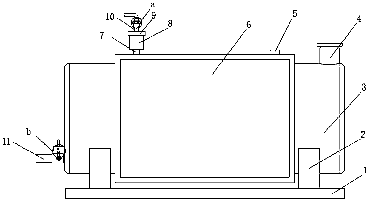
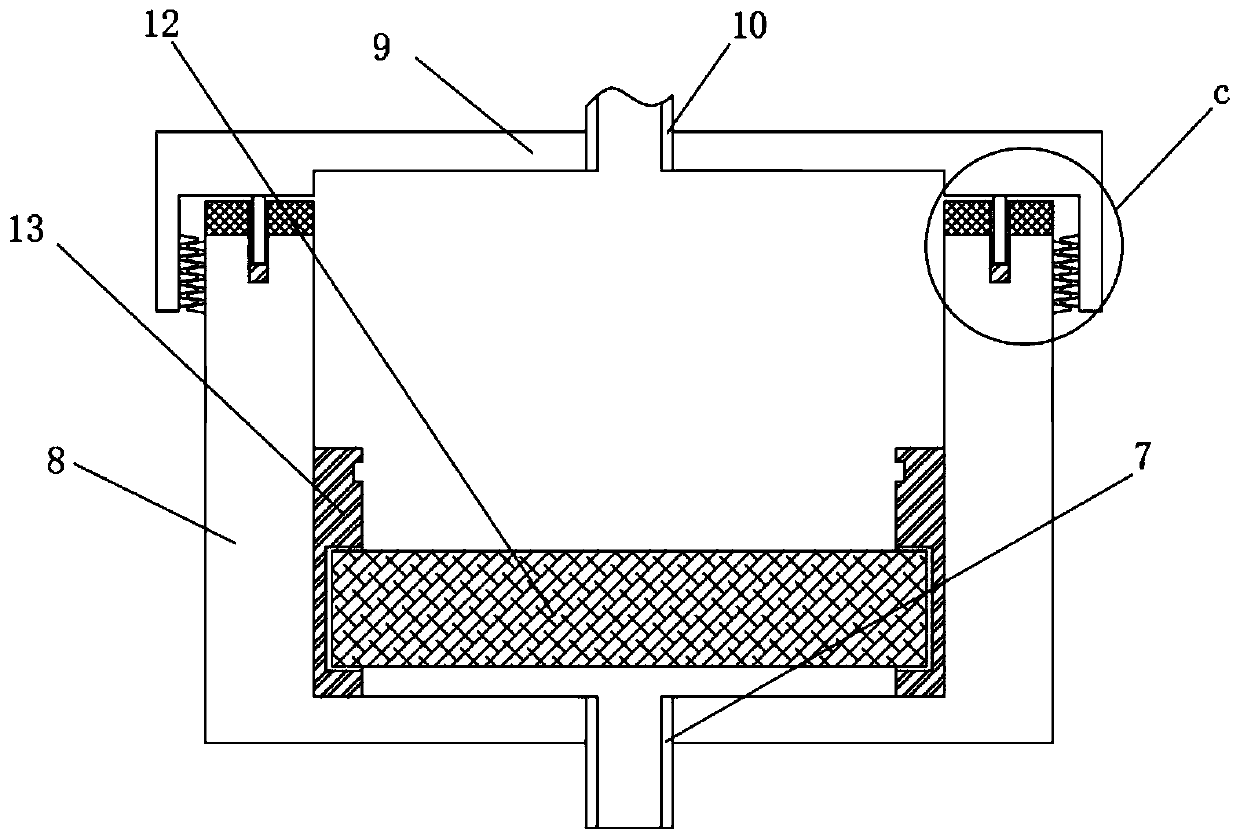
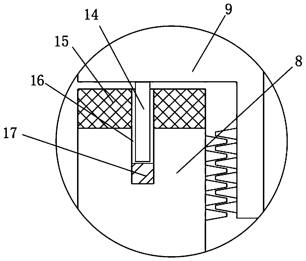
[0028] see Figure 1-Figure 9 , the present invention provides a technical solution: a lubricating oil storage tank, including a storage tank 3, a heating cylinder 6 is arranged on the outside of the storage tank 3, a support 2 is located on both sides of the bottom end of the heating cylinder 6, and the bottom of the support 2 A base 1 is provided at the end of the heating cylinder 6, and a liquid outlet pipe 5 and a liquid inlet pipe 7 are respectively arran...


PUM


Abstract

The invention discloses a lubricating oil storage tank. The lubricating oil storage tank comprises a storage tank, a heating cylinder is arranged at the outer side of the storage tank, supports are arranged on the two sides of the bottom end of the storage tank, a base is arranged at the bottom ends of the supports, a liquid outlet pipe and a liquid inlet pipe are arranged at two sides of the topend of the heating cylinder correspondingly, a filter cartridge is arranged at the top end of the liquid inlet pipe, a fixing cover is arranged at the top end of the filter cartridge, a first pipelineis arranged at the top end of the fixing cover, the bottom end of the first pipeline penetrates through the fixing cover, the liquid inlet pipe penetrates through the filter cartridge, a silica gel sleeve is arranged on the inner wall of the filter cartridge, a filter screen is arranged at the bottom end of the inner wall of the silica gel sleeve, an annular groove is formed in the top end of theinner wall of the silica gel sleeve, a first sealing gasket is arranged on the top end surface of the filter cartridge, and a sealing groove is formed in the top end surface of the filter cartridge.The silica gel sleeve is additionally arranged at the outer side of the filter screen, so that a worker can replace the filter screen conveniently, the liquid inlet efficiency of the liquid inlet pipeis further improved, and the heating efficiency of the heating cartridge on the storage tank is further improved.

Description

technical field [0001] The invention belongs to the technical field of oil storage tanks, and in particular relates to a lubricating oil storage tank. Background technique [0002] Lubricating oil is a liquid or semi-solid lubricant used in various types of automobiles and mechanical equipment to reduce friction and protect machinery and processed parts. It mainly plays the role of lubrication, auxiliary cooling, rust prevention, cleaning, sealing and buffering. Between two relatively moving objects, it can reduce the friction and wear of the two objects due to contact. In the process of lubricating oil production and manufacturing, the mass-produced lubricating oil is generally stored in the oil storage tank first, and then It is troublesome to replace the filter screen of the filter cartridge in the existing oil storage tank, which reduces the liquid inlet efficiency of the liquid inlet pipe, which leads to the problem of low heating efficiency of the heating cylinder for ...

Claims


Application Information

Patent Timeline
Patent Type & Authority Applications(China)
IPC IPC(8): B65D88/74B65D90/54B65D90/00
CPCB65D88/74B65D90/00B65D90/54
Inventor 谢飞
Owner XUZHOU HAITIAN PETROCHEM
Why Eureka
Try Eureka