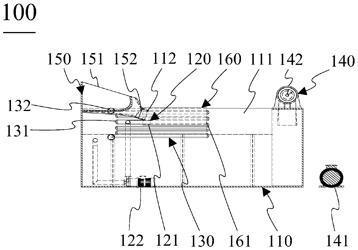
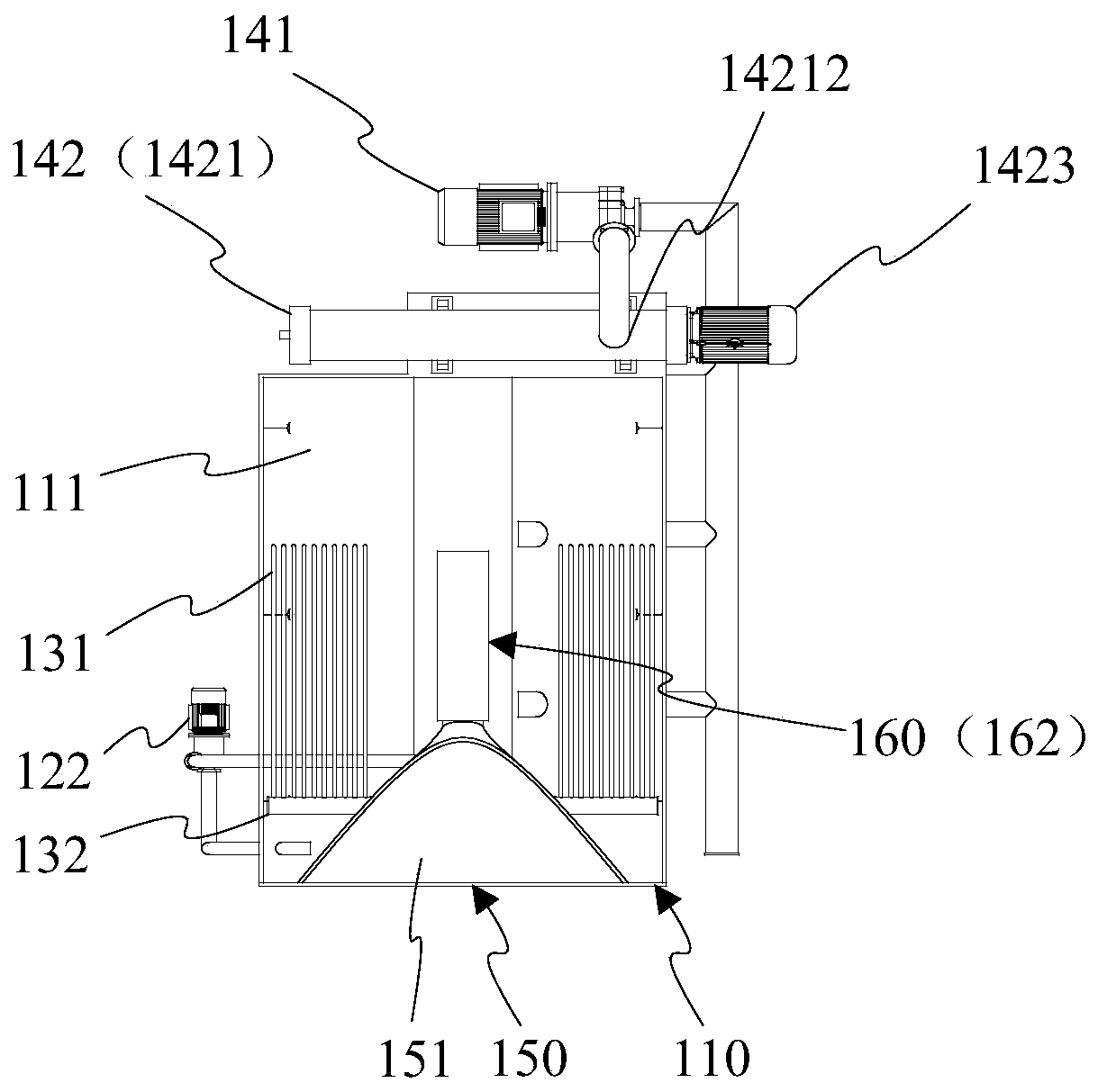
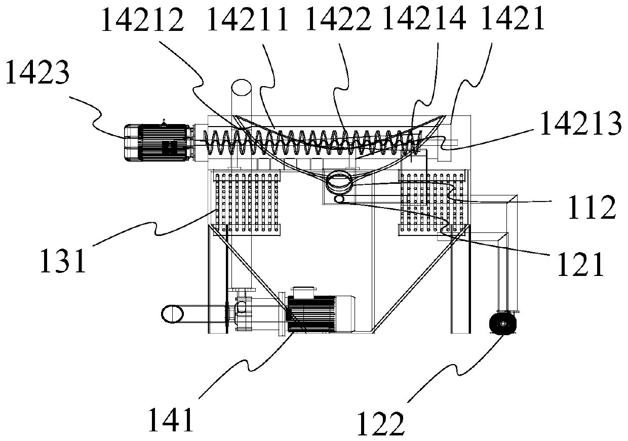
Water quenching device for electric furnace slag

An electric furnace slag and water cavity technology, which is applied in the field of steel slag treatment, can solve the problems of poor working conditions, high water consumption, and great influence on electric furnace production, and achieves the effect of compact structure and reduction of water vapor generation.

Active Publication Date: 2020-04-14
北京天朗致达节能环保股份有限公司
View PDF8 Cites 1 Cited by
  • Summary
  • Abstract
  • Description
  • Claims
  • Application Information

AI Technical Summary

Problems solved by technology

The waste slag process is to pour high-temperature liquid electric furnace slag directly into the slag dump, and draw water to cool it in the slag dump. This process occupies a large area of ​​land, poor working conditions, long treatment cycle, and serious environmental pollution; The quenching process is to install a water quenching device in front of the electric furnace. The water quenching device is equipped with a funnel, a slag chute and a water spray pipe. When the electric furnace slag is discharged, the device is hung under the operating platform of the electric furnace. Heat exchange with water in the tank for water quenching. After water quenching, the electric furnace slag is flushed into the slag flushing pool in front of the furnace. This process cannot stably control the flow of liquid slag, and small explosions will occur, and the steam emission is large. Greater impact
The tipping tank-water pool process is to pour the liquid high-temperature electric furnace slag in the steel drum into the slag tank on the automatic slag dumping vehicle, and the slag truck automatically drives to the water quenching pool outside the workshop, and the slag tank is tipped over for water quenching. The process has a high degree of automation, but the working area is in an open space, the steam discharge is large, and the water consumption is high

Method used


Image

  • Water quenching device for electric furnace slag
  • Water quenching device for electric furnace slag
  • Water quenching device for electric furnace slag

Examples


Embodiment Construction

[0064] In order to have a clearer understanding of the technical features, purposes and effects of the invention, the specific implementation manners of the present invention will now be described with reference to the accompanying drawings, in which the same reference numerals represent the same parts.

[0065] In this article, "schematic" means "serving as an example, example or illustration", and any illustration or implementation described as "schematic" should not be interpreted as a more preferred or more advantageous Technical solutions.

[0066] In order to make the drawings concise, the figures in each figure only schematically show the relevant parts of the present invention, and do not represent the actual structure of the product. In addition, to make the drawings concise and easy to understand, in some drawings, only one of the components having the same structure or function is schematically shown, or only one of them is marked.

[0067] In this article, "first"...


PUM


Abstract

The invention discloses a water quenching device for electric furnace slag. The device comprises a main shell, a crushing and cooling unit, a heat exchange unit and a dehydration unit, and is compactin structure, simple and reliable, wherein the main shell is provided with a water cavity and a main material inlet located below a liquid level, the crushing and cooling unit is used for crushing andcooling liquid-state steel slag from the main material inlet, the crushing and cooling process is located below the liquid level so as to effectively control the generation of water vapor, the heat exchange unit controls the water temperature of the water cavity so as to further control the generation of steam, and the dehydration unit is used for dehydrating the water-quenched slag deposited atthe bottom of the water cavity so as to obtain dehydrated finished steel slag, so that the generation of water vapor can be effectively reduced so as to achieve the purposes of water saving and emission reducing.

Description

technical field [0001] The invention relates to steel slag treatment technology, in particular to an electric furnace slag water purification device. Background technique [0002] With the increase of my country's steel production year by year, the production of steel slag also increases. Disposal of steel slag not only causes waste of metallic iron resources, but also causes environmental pollution. The random accumulation of steel slag not only occupies a large amount of land resources, but also causes damage to the surrounding soil and water systems. [0003] At present, there are many ways to treat high-temperature liquid electric furnace slag, such as spoiling slag process, water quenching process before furnace, tipping tank-water pool process, etc. The waste slag process is to pour high-temperature liquid electric furnace slag directly into the slag dump, and draw water to cool it in the slag dump. This process occupies a large area of ​​land, poor working condition...

Claims


Application Information

Patent Timeline
IPC IPC(8): C21B3/06C21B3/08
CPCC21B3/06C21B3/08C21B2400/024C21B2400/066Y02W30/50
Inventor 吴海磊张阳王爽
Owner 北京天朗致达节能环保股份有限公司
Why Eureka
Try Eureka