Spliced suspended ceiling

A technology for suspended ceilings and clamping grooves, applied in the direction of ceilings, building components, buildings, etc., can solve the problems of easy deformation, poor flatness and poor stability of suspended ceilings, avoid deformation or warping, improve structural stability, and increase structure. the effect of strength

Pending Publication Date: 2020-04-14
ZHEJIANG YASHA DECORATION
View PDF0 Cites 3 Cited by
  • Summary
  • Abstract
  • Description
  • Claims
  • Application Information

AI Technical Summary

Problems solved by technology

[0003] In the prior art, the adjacent ceiling boards are generally installed on the ceiling connection structure by side slotting or screw fastening at the butt joint, and the slotting or screw connection has the problem of damaging the side edge structure of the boards. , and the side edges of the boards are installed on the ceiling connection structure, and the force is relatively large, which is prone to deformation or warping, and there is a problem of poor stability. The ceiling formed by splicing multiple boards in sequence has the problem of poor flatness, which affects the decoration effect

Method used


Image

  • Spliced suspended ceiling
  • Spliced suspended ceiling
  • Spliced suspended ceiling

Examples


Embodiment Construction

[0029] The directional terms such as up, down, left, right, front, back, front, back, top, and bottom that are mentioned or may be mentioned in this specification are defined relative to the structures shown in the drawings. The words " "Inside" and "outside" respectively refer to the direction toward or away from the geometric center of a specific component. They are relative concepts, so they may change accordingly according to their different positions and different usage states. Accordingly, these or other directional terms should not be construed as limiting terms.

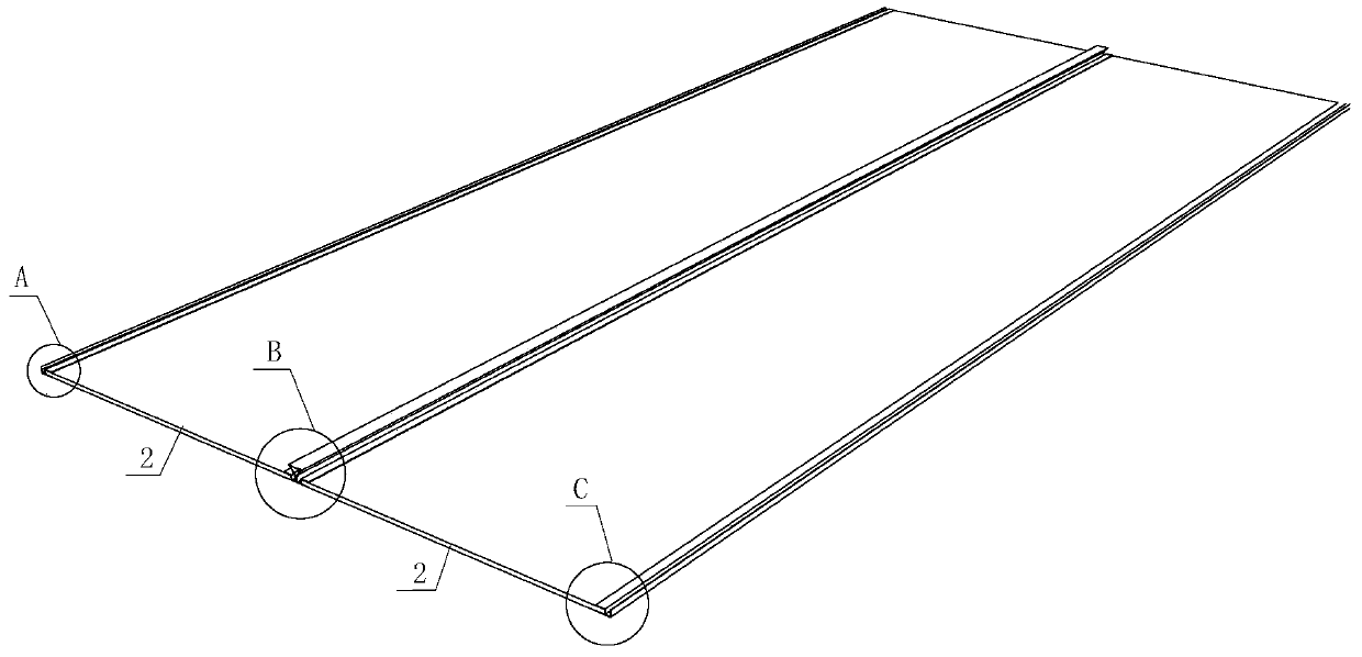
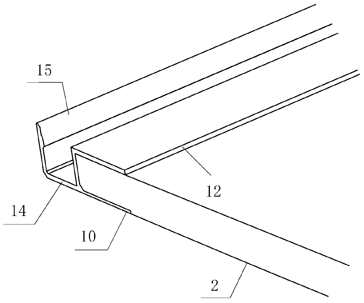
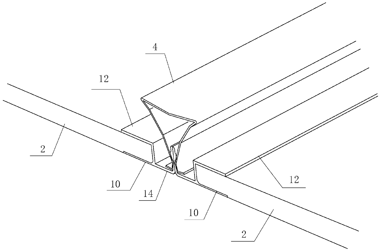
[0030] Such as Figure 1 to Figure 11 As shown, the spliced ​​suspended ceiling provided by the embodiment of the present invention includes: at least two plate assemblies and the hanging keel 4 .

[0031] Please also refer to Figure 1 to Figure 11 , at least two plate assemblies are arranged in a row, the hanging keel 4 includes a slot 46; any of the plate assemblies includes a base plate 2 and a plate re...


PUM


Abstract

The invention discloses a spliced suspended ceiling. The spliced suspended ceiling comprises at least two plate assemblies and a hanging connection keel. The at least two plate assemblies are arrangedin an alignment mode. The hanging connection keel comprises a clamping groove. Each plate assembly comprises a base plate and plate reinforcing parts. Each plate reinforcing part comprises a clampingconnection portion and an installation portion. Each base plate comprises a first installation end and a second installation end. Each clamping connection portion comprises a first clamping plate, asecond clamping plate and a third clamping plate. The first clamping plates, the second clamping plates and the third clamping plates are combined together to define clamping connection grooves. Eachinstallation portion comprises a limiting plate and an installation plate. The limiting plates and the installation plates are connected with each other. The plate reinforcing parts are connected withthe first installation ends and the second installation ends, and each first installation end and the corresponding second installation end are clamped into the two corresponding clamping connectiongrooves in a connection mode. After every two adjacent plate assemblies are connected in a butt joint mode, two installation plates are attached and connected and then are clamped into the clamping groove in a connection mode together. According to the spliced suspended ceiling, the phenomenon that the edges of plates deform or warp is avoided, and the smoothness of the suspended ceiling is improved.

Description

technical field [0001] The invention relates to the technical field of architectural decoration, in particular to a spliced ​​suspended ceiling. Background technique [0002] Suspended ceiling is one of the most common decorative structures in interior decoration. The suspended ceiling structure usually includes a suspended ceiling connection structure and a ceiling plate. The suspended ceiling connection structure is used to connect the ceiling plate and fix the ceiling plate on the building. [0003] In the prior art, the adjacent ceiling boards are generally installed on the ceiling connection structure at the butt joint by means of slotting on the side or fastening with screws. Both the slotting and the screw connection have the problem of damaging the side edge structure of the boards. , and the side edges of the boards are mounted on the ceiling connection structure and are subjected to a large force, which is prone to deformation or warping, and there is a problem of ...

Claims


Application Information

Patent Timeline
Patent Type & Authority Applications(China)
IPC IPC(8): E04B9/28E04B9/06
CPCE04B9/06E04B9/065E04B9/28
Inventor 丁欣欣丁泽成王文广周东珊骆飞烨步挺
Owner ZHEJIANG YASHA DECORATION
Why Eureka
Try Eureka