Wall cement troweling machine
A technology of troweling machine and cement, which is applied in the direction of construction and building construction, and can solve problems such as inconvenient use and inability to trowel concrete walls
- Summary
- Abstract
- Description
- Claims
- Application Information
AI Technical Summary
Problems solved by technology
Method used
Image

Examples
Embodiment 1
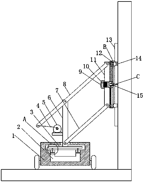
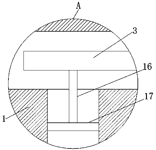
[0028] refer to Figure 1-6 , a wall cement troweling machine, comprising a main body 1, rollers are provided on both sides of the main body 1, a water storage tank 2 is provided at the bottom of the main body 1, a first cavity is provided at the top of the main body 1, and the main body 1 is provided in the water storage tank 2 and the first cavity are provided with two first through holes, the main body 1 is provided with a sealing plate 17 at the two first through holes, the main body 1 is provided with a rotating plate 3 at the first cavity, and the rotating plate Both sides of the 3 bottom end are welded with a moving rod 16, and the middle part of the top of the rotating plate 3 is welded with a supporting column 6, and the middle part and the top of the supporting column 6 are rotatably connected with a first connecting rod 7 and a second connecting rod 8 respectively. One end of the rod 7 and the second connecting rod 8 is rotatably connected with the same fixed body 1...
Embodiment 2
[0039] refer to Figure 7 , a wall cement troweling machine. Compared with Embodiment 1, in order to enhance the practicability of the device, the device can walk in a straight line along the wall. One side of the main body 1 is provided with an infrared rangefinder 25, and the main body The bottom end of 1 is provided with steering mechanism and single-chip microcomputer 26, and all by electrical connection between single-chip microcomputer 26 and infrared rangefinder 25 and steering mechanism, infrared rangefinder 25 can determine the distance between main body 1 and the wall, when main body 1 When the distance between the main body 1 and the wall changes, the single-chip microcomputer 26 receives the signal and turns the steering mechanism so that the distance between the main body 1 and the wall is always fixed, ensuring the stability of the rotating plate 13 during work.
[0040] When in use, the main body 1 can walk on the ground through the rollers, the support column 6...
PUM
 Abstract
Description
Claims
Application Information
 - R&D
- Intellectual Property
- Life Sciences
- Materials
- Tech Scout
- Unparalleled Data Quality
- Higher Quality Content
- 60% Fewer Hallucinations
Browse by: Latest US Patents, China's latest patents, Technical Efficacy Thesaurus, Application Domain, Technology Topic, Popular Technical Reports.
© 2025 PatSnap. All rights reserved.Legal|Privacy policy|Modern Slavery Act Transparency Statement|Sitemap|About US| Contact US: help@patsnap.com